Types of Lightning Protection Systems LPS
Lightning protection systems for buildings and installations may be divided into three principal types as follows:
1- LPS for Protection for buildings and installations against direct strike by lightning, which includes:
A- Conventional lightning protection system, which includes:
- Franklin Rod LPS,
- Franklin/Faraday Cage LPS.
B- Non-Conventional lightning protection system, which includes:
a- Active Attraction LPS, which includes:
- Improved single mast system (Blunt Ended Rods),
- Early streamer Emission System.
b- Active Prevention/Elimination LPS, which includes:
- Charge Transfer System (CTS),
- Dissipation Array System (DAS).
2- LPS for Protection against overvoltage on incoming conductors and conductor systems,
3- LPS for Protection against the electromagnetic pulse of the lightning.
|
And, I explained the Conventional Lightning Protection System parts and components in the following Articles:
- Improved single mast system (Blunt Ended Rods),
- Early streamer Emission System.
- Differences in Lightning Protection Technologies,
- Principle of Operation for Active Prevention/Elimination LPS,
- Types Of Lightning Elimination/Prevention Systems.
Also, In Article " Non-Conventional Lightning Protection System – Part Four ", I explained the following points:
- Protected Area Considerations in Dissipation Array Systems,
- DAS Selection Criteria,
- SBI and SBT Application Criteria.
Today, I will explain Some Examples for Typical Designs of DAS, SBT and SBI.
For more information, you can review the following Articles:
First: Examples for Typical Designs of Dissipation Array Systems (DAS)
|
1- DAS for A Basic Building Block
 |
| FIG. 1 |
Referring first to FIG. 1 which is a schematic of the basic building block for most Dissipation Array systems (DAS), which consists of:
- The multipoint dissipation wires (30 and 31) which are a basic
DAS building block,
- Ionizing members (32 and 42) contained in the multipoint
dissipation wires (30 and 31).
Design parameters:
The parametric values of the ionizing members (32 and 42), which are varied to achieve the required performances as a function of the specific DAS application will be:
- The height (L),
- Space (s),
And there is a third parametric
value; the separation distance (d) between adjacent multipoint dissipating
wires (30 and 31).
Recommendations For Design Parameters:
The design parameters must be adjusted to properly perform in a
given application and DAS configuration as follows:
- The ionizing members (32 and 42) parameter height (L) should be
in excess of 7 cm. Optimum performance occurs with 11-12 cm, where (s) is in
the range of 7 to 12 cm. Longer heights (L) yield little improvement. Shorter
heights (L) become less effective, particularly below 5 cm.
- Ionizing members (32 and 42) having spacings (s) between 5 and 20
cm perform best. However, the best spacing (s) is also dependent on the
separation distance (d) between adjacent multipoint dissipating wires (30 and
31). The smaller the distance (d) calls for the smaller spacing (s) to the
lower limit of about 5 cm for maximum performance.
- The separation distance (d) should be no less than about 10 cm
but can extend to several meters depending on the application. Ionizing
member (32) may be used for the closer separation distances d, and ionizing
member (42) for distances d in excess of 20 cm. Other arrangements of these Parameters
are feasible, but will function with less efficiency.
|
2- DAS for A Typical Electrical Overhead
Distribution Line
 |
| Paragon Array |
Paragon
Array is commonly
used on transmission and distribution lines.
 |
| FIG. 2 |
Referring
to FIG. 2A, a typical electrical overhead distribution line comprising of:
- Overhead distribution line (10),
- Conductors (16),
- The multipoint dissipation wires (30) contain ionizing members (32),
- Poles (12) erected with conventional spacings (14) from each
other and carrying crossarms (12A) with insulators (18) is depicted,
- A dual dissipator system (DDS) (20) is shown with its mounting
member assembly (22),
- The mounting member assembly (22) includes a vertical strut (24)
having a horizontal spacer (26) normally mounted at its midpoint on top of
the strut (24),
- A grounding wire (28).
FIG. 2A is a perspective view of a DAS as applied to an electrical overhead transmission/distribution line for a random length thereof. This design is also called the Dual Dissipator System (DDS).
FIG. 2B is a perspective view of an enlarged detail length of the portion 2 of the DDS shown in FIG. 2A.
Recommendations For Design Parameters:
- The height of horizontal spacer (26) above conductors (16) is
generally in excess of 1/2 meter. The mounting member assembly (22) may be in
the form of the tee illustrated or other shapes appropriate to achieve the
required elevation above the conductors (16) and the spacing between the
multipoint dissipation wires (30).
- The length of the horizontal spacer (26) is selected to provide
optimum distance (d) between the multipoint dissipation wires (30) as shown
in FIG. 1. Distance (d) should be not less than 1/3 meter nor more than one
meter for a single set of transmission or distribution lines for best
performance. Although other spacing will function to some degree, there is
created a risk of failure to prevent the stroke.
- Connections to a grounding wire (28) must be made to the mounting
member assembly (22) or directly to the multipoint dissipation wires (30).
Additional multipoint dissipation wires (30) may be used where more than one
set of phase conductors are used or large separation distances exist between
them. Vertically constructed lines may be protected in a similar manner.
|
3- DAS for Towers, Poles and Stacks with a
Hemispherical Dissipation Array
 |
| Hemisphere Array |
Hemisphere Array Can be placed on any industrial or commercial structure, including poles, buildings, and towers.
 |
| FIG. 3 |
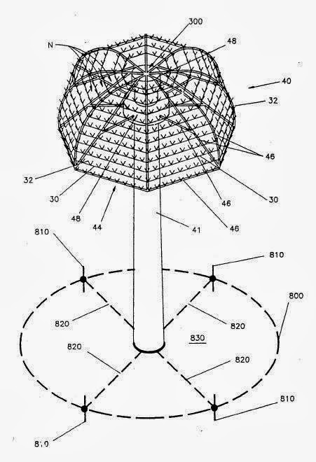
FIG. 3 is a front elevational view of a hemispherically-shaped array mounted on a lightning mast, tower, pole, or a similar structure.
Referring now to FIG. 3, a hemispherical dissipation array (40) is designed for convenient installation on many types of supporting structures such as towers, poles and stacks. The Dissipation Array (40) is composed of:
- The ground current collector wire (800) buried to a depth of about 25 centimeters and the short, about one meter long, rods 810 connected at one end with wire 800,
- The rods (810) are spaced at intervals of about ten meters,
- The enclosed area (830) is further integrated by a net of cross conductors (820). Any surface structures (not shown) inside area 830 would also connect to cross conductors 820. The enclosed area 830 becomes an integrated electrical island which is surrounded by less conductive soil (not shown).
- Dissipation array (40) with extended skirt (44) downward to nearly a full 90 degrees below the apex (300),
- In addition, the diameter of the skirt (44) and the wire spacing (N) was changed to provide the optimum number of ionizing members (32) while optimizing the production of ions. To achieve these objectives, a skirt (44) comprises industrial structural members (46), top zone (48) and pole (41),
- Dissipation wires 30 (or 31) are arranged in parallel.
Recommendations For Design Parameters:
- Space N ranges from 5 to 20 cm. Fifteen cm for N is optimum for most applications while other spacings will function with reduced performance. Skirt (44) may take on various lengths to height ratios and curvature gradients. It may also have various size flat or open sections in its center to accommodate the mounting tower, pole or stack.
- Where used alone, this DAS configuration must provide a minimum dissipation area of about 15 square meters. The requisite ionizing member (32) density ranges from 1000 to 2000 per square meter.
- A hemispherical dissipation array system for preventing a lightning stroke between a cloud and a protected facility, comprising:
- at least one discrete hemispherical ionizer structure rising above the earth's surface and the protected facility, thereby forming a uniform field shape over the protected facility,
- an endless ground current collector structure connected to the ionizer structure and having at least one downwardly extending grounded charge collecting rod, thereby forming an electrically floating island around the protected facility,
- Said ionizer structure having a skirt extending downwardly approximately 90 degrees below the apex,
- said ionizer structure further comprising a series of parallel wires spaced apart a distance ranging from 5 to 20 cm, thereby forming an umbrella shaped hemispherical ionizer structure of about 15 square meters,
- Said parallel wires having a number of equally spaced ionizer member points ranging from 1000 to 2000 per square meter,
- Said ionizer member points each having two wire segments angularly facing upward and having a length of approximately 12 cm and said ionizer member points having equidistant spacing from one another ranging from 5 to 20 cm.
|
4- Tall Towers, Buildings, Tanks and Other Structures
 |
| Trapezoid Array |
Trapezoid Array can be used on industrial and commercial structures with guy ropes.
 |
| FIG. 4 |
FIG. 4 is a top perspective view of a typical pyramidal or trapazoidal array for use on the top of an existing structure to be protected.
FIG. 4 presents an alternate design (50) for protecting tall towers, buildings, tanks and other structures where it can be conveniently assembled. This DAS design (50) is made up of:
- Trapezoidal shaped panels (58-30-62). Usually one, two, three or four panels are used for the DAS.
- In FIG. 4 the panel (58.30.62) is affixed to a support structure, tower (52), at the upper spreader bar (58).
- Spreader bar (58) has a plurality of holes (60) near its lower edge.
- A bottom spreader (62) is strung across and fastened to the protected structure (56) at anchor points (64).
- Dissipation wires (30) have ionizing members (32). Dissipation wires (30) are strung from holes (60) to corresponding anchor points (64') on the bottom spreader (62) thus completing the subject DAS.
- The dissipation wire 30.
- Interim spreaders (66) may be made of dissipation wire (30) to assure the desired separation for the full length of each dissipation panel (58-30-62).
 |
| FIG. 5 |
FIG. 5 is a schematic top plan view of the full array of the design shown in FIG. 4.
FIG. 5 illustrates another DAS configuration using multiple panels from FIG. 4. The angle of these panels may be varied from 10 degrees to over 45 degrees away from the support structure (52).
Recommendations For Design Parameters:
- The dissipation wire 30 spacings N are set so that the separation distance N is in excess of 1/2 meter for at least 80 percent of the length of dissipation wire (30).
- A dissipation array system for preventing a lightning stroke between a cloud and a protected facility, comprising:
- At least one trapezoidal panel mounted in a vertical manner atop the protected facility and connected to ground;
- said trapezoidal panel comprising converging wires spaced apart a distance in excess of 1/2 meter for at least 80 percent of their lengths;
- Said converging wires each including ionizer points spaced apart distances ranging from 5 to 20 cm, wherein said parallel wires cause the electrical field between the cloud and the protected area to be bent over the protected area and partially dissipated to atmosphere, thereby preventing a lightning stroke.
|
5- Structures Having a Circular or a Polygonal Outline like Tanks
 |
| FIG. 6 |
FIG. 6 is a top perspective view of the DAS configuration used for flammable storage.
The DAS configuration (70) in FIG. 6 is suited for the protection of structures having a circular or a polygonal outline. A flammable storage reservoir (72) is shown for this design. DAS consists of:
- T-shaped supports (74) are installed along the upper periphery of the reservoir (72),
- A plurality of dissipation wires (30) having the ionizing members (32) are fastened to the horizontal leg of said T-shaped supports (74). Each dissipation wire 30 forms a closed-circuit type circular loop.
Recommendations For Design Parameters:
- Multiple circular loops are positioned concentrically at a discrete, predetermined radial distance N.
- Each union of dissipation wire loops (30) and each connection between dissipation wire loops (30) and T. shaped supports (74) and between the latter and the reservoir (72) are securely bonded.
- The reservoir (72) is securely grounded.
- The FIG. 6 configuration requires a minimum of 3 dissipation wires (30) for tanks in excess of 100 ft. in diameter.
- Four dissipation wires (30) are required for smaller tanks.
- For best results, the dissipation wires (30) should be separated by a distance N ranging from 15 to 20 cm. The ionizing members (32) should be at 15 cm separation. The height (l) should be 10 cm as shown in FIG. 1. Ionizing members (32) can be seen to point angularly away from the protected facility (899).
 |
| FIG. 7 |
FIG. 7 is a top perspective view of a conically-shaped DAS used for the protection of a cone roof flammable storage reservoir.
 |
| Conic Array |
To assure proper protection of conical or flat roof reservoirs for flammables or other sensitive products, the design (80) in FIG. 7 is appropriate and includes:
- A tower (82) (or pole) is mounted axially and upwardly in the center of the top (84) of the reservoir (86),
- A bracket (88) mounted on the top of the tower (82) is adapted for the fastening of the dissipation wires (30) having ionizing members (32),
- Dissipation wires (30) are strung, fastened and bonded to suitable attachment positions (90) along the top periphery of the reservoir (86).
Recommendations For Design Parameters:
- All connections between the dissipation wires (30) and the respective points of attachment are securely bonded directly as well as indirectly to the reservoir (86).
- Reservoir (86) is securely grounded.
- The dissipation wires (30) separation criteria, ionizing member spacing, and ionizing member height are somewhat more flexible but should range between the values identified in FIG. 4 which was a top perspective view of a typical pyramidal or trapazoidal array for use on the top of an existing structure to be protected.
|
Second: Examples for Typical
Designs of The Spline Ball Ionizer (SBI)
|
1- The Spline Ball Ionizer (33)
 |
| FIG. 8 |
FIG. 8 is a front elevational view of an alternate form of multipoint dissipator, the Spline Ball Ionizer (33). The Spline Ball Ionizer is used autonomously or in concert with others, to make up a DAS for various applications where low cost protection is required.
It is relatively low cost to manufacture and install. The Spline Ball Ionizer (33) comprises the following:
- A stem (90),
- A ball (91),
- The ball (91) is composed of multiple branches (92). Branches (92) fold downward around stem (90) for ease of packaging and installation.
Recommendations For Design Parameters:
- Ball (91) and stem (90) are electrically conductive, preferably made of copper.
- The diameter (w) of ball (91) ranges from 20 to 50 inches varying with the width of the tower it protects.
 |
| FIG. 9 |
FIG. 9 is a top perspective view of the Spline Ball Ionizer of FIG. 8 protecting a tower.
FIG. 9 shows a tower (100) holding an instrument bar (101) high above the ground. The Spline Ball (33) is mounted directly to the tower (100) and is grounded thereto.
In operation, the Spline Ball (33) dissipates the electrostatic charge caused by a passing cloud. The electrostatic charge passing along the ground is raised up and over the tower (100) by means of branches (92) which function as ionizer points. Dissipation of the ground charge is also accomplished, thus preventing a lightning stroke on the tower (100). The spline Ball (33) is also a cost effective way to protect a house.
Recommendations For Design Parameters:
- The height (H) of the lowermost portion of the ball (91) above the instrument bar (101) should equal the diameter (w) of the ball (91).
- A Dissipation Array System for preventing a lightning stroke between a cloud and a protected facility, comprising:
- Said ball comprising conducting branches emanating outward from a central point;
- A grounded mounting stem holding said ball from its central point above the protected facility;
- Said branches folding downward from hipping;
- Said grounded mounting stem being of a length allowing the bottom of the ball to be held at a height above the protected facility equal tot eh diameter of the ball.
|
Third: Examples for Typical
Designs of Spline Ball Terminal (SBT)
|
1- Spline Ball Terminal (SBT) (80)
 |
| Spline Ball Terminal (SBT) (80) |
 |
| FIG. 10 |
FIG. 10(a) is a front elevational view of a spline ball terminal (SBT) before the splines are arrayed into their functional positions.
FIG. 10 (b) is a perspective view of an SBT showing the common ground connector.
FIGS. 10a and 10b and 11a and 11b show the Spline Ball Terminal (SBT) 80 which comprises of:
- The SBT has a number of splines 40 centrally affixed at point 41,
- Shaft 82,
- Threaded hub 83,
- The spline dissipation unit 84 holds the splines 40 together,
- The base 88 supports the threaded hub 83,
- Mounting holes 89 are used to firmly attach the SBT to the protected facility,
- A ground cable 85 passes through the connector fitting 86 and a bolt 87 secures the ground cable 85 to the connector fitting 86.
Recommendations For Design Parameters:
- The ideal number of splines is one hundred five (105). Each spline must be at least 1/10 inch in diameter or greater in order to withstand the electric power of an average stroke.
- Spline 40 is oriented at least every 5 degrees in azimuth for the full 360 degrees and a full 120 degrees in elevation. As a result, there is no direction from which a leader can approach that would not have a collective point oriented directly toward it with many nearby backup points.
- Each spline 40 is at least 12 inches long.
- The shaft 82 is at least 10 inches long.
- The threaded hub 83 has a minimum wall thickness of 1/16 inch measured at the base of the threads. The spline dissipation unit 84 holds the splines 40 together in a common electrical bond.
- A ground cable 85 passes through the connector fitting 86 for a length of at least 1 1/2 inches surrounded on all sides by the connector fitting 86.
 |
| FIG. 11 |
FIG. 11(a) is a front elevational view of a side mounted SBT with the splines in the shipping position.
FIG. 11(b) is a top perspective view of a side mounted SBT with the splines in a functional position.
FIGS. 11a and 11b merely show a different base 188 for side mounting on a wall 501 on a protected facility 500. Bolt 187 fastens the ground cable 85 in the connector fitting 186.
Application Of Spline Ball Terminal (SBT) (80) On Buildings
 |
| Application Of Spline Ball Terminal (SBT) (80) On Buildings |
 |
| FIG. 12 |
- FIG. 12 is a perspective view of a protected facility having a network of interconnected SBT's, deployed to satisfy the existing standards.
- FIG. 12 shows a series of SBT's 80 mounted atop the roof of a protected facility 1000. A ground cable 85 connects all the SBT's to a common ground 1001. The net effect of multiple SBT's is to create a number of ionization points 40 over the protected facility.
- The more the SBT's the better the chance of preventing all potential strokes to the protected facility 1000. The more the ionization points 40 the faster the dissipation of the induced charge and the better the chance of stroke prevention.
- The spacing between SBT's on a flat roof to provide dissipation and stroke collection capabilities shall be twenty to twenty-five feet. Furthermore, there shall be a 50 foot maximum distance between SBT's anywhere on the roof. Therefore, large roofs shall require multiple strings of SBT's.
- Thus, the SBT is a hybrid stroke prevention system with highly efficient lightning rod collection capabilities. The SBT meets UL standards for lightning rods or air terminals.
|
Important Note
The above designs are typical, and variations, modifications and alterations for these designs are feasible within the spirit of its recommendations.
|
In the next Article, I will explain The Claimed Advantages for Dissipation Array System (DAS) And Arguments against Them. Please, keep following.


No comments:
Post a Comment