Conventional Lightning Protection System Components – Part One


In Article 
 Introduction to Lightning System Design- Part One ", I listed all terms, abbreviations and Symbols used in lightning field.

Also, in Article 
Introduction to Lightning System Design- Part Two ", I answered the following questions:
  • What is Lightning? 
  • What are the types of Lightning flashes?
  • What is the shape of The Lightning Waveform?
  • How Lightning strikes can affect the electrical and/or electronic systems of a building?
  • What are the main effects of Lightning?


And in Article " Types Of Lightning Protection Systems LPS ", I list the main types of Lightning Protection Systems as follows:


Types of Lightning Protection Systems LPS


Types of Lightning Protection Systems LPS

Lightning protection systems for buildings and installations may be divided into three principal types as follows:

  1. LPS for Protection for buildings and installations against direct strike by lightning,
  2. LPS for Protection against overvoltage on incoming conductors and conductor systems,
  3. LPS for Protection against the electromagnetic pulse of the lightning.


1- LPS for Protection for buildings and installations
against direct strike by lightning

This type of LPS protects the building from damage by direct strike lightning but doesn’t prevent the lightning striking the building. This type of LPS can be divided into:-

  1. Conventional lightning protection system,
  2. Non-Conventional lightning protection system.


1.1 Types of Conventional Lightning Protection System

The Conventional Lightning Protection System includes (2) different types as follows:

  1. Franklin Rod LPS,
  2. Franklin/Faraday Cage LPS.


1.2 Types of Non-Conventional Lightning Protection System

The Conventional Lightning Protection System includes (2) different types as follows:

1- Active Attraction LPS, which includes:

  • Improved single mast system (Blunt Ended Rods),
  • Early streamer Emission System.


2- Active Prevention/Elimination LPS, which includes:

  • Charge Transfer System (CTS),
  • Dissipation Array System (DAS).


Notes on different Types of Lightning Protection Systems LPS

Each system’s design requires the following:

  • The air terminal or strike termination device must be positioned so that it is the highest point on the structure.
  • The lightning protection system must be solidly and permanently grounded. Poor or high resistance connections to ground are the leading cause of lightning system failure for each one of these systems.
  • None of these systems claims to protect against 100% of the possibility of a lightning stroke arriving near protective area. A compromise must be made between protection and economics.


Today, I will explain the Conventional Lightning Protection System LPS Components.


Conventional Lightning Protection System LPS Components


The Correct Choice Of Lightning Protection Components (LPC)


  • The correct choice of material, configuration and dimensions of the lightning protection components is essential when linking the various elements of an LPS together. 
  • The designer/user needs to know that the components, conductors, earth electrodes etc will meet the highest levels when it comes to durability, long term exposure to the environmental elements and perhaps most importantly of all, the ability to dissipate the lightning current safely and harmlessly to earth.
  • Various standards series have been compiled with this very much in mind. At present these standards are as follows:


Standards for Lightning Protection Systems


1- Within Europe:

Various standards series have been issued by (2) National Committees which are:

  1. The European Committee for Electrotechnical Standardisation (CENELEC).
  2. The International Electrotechnical Commission (IEC)


The CENELEC has released the EN 50164 series of standards. The EN 50164 series are component standards to which the manufacturers and suppliers of lightning protection components should test their products to verify design and quality. The EN 50164 series currently comprises of:

  • EN 50164-1 Lightning protection components (LPC) – Part 1: Requirements for connection components,
  • EN 50164-2 Lightning protection components (LPC) – Part 2: Requirements for conductors and earth electrodes,
  • EN 50164-3 Lightning protection components (LPC) – Part 3: Requirements for isolating spark gaps,
  • EN 50164-4: Lightning Protection Components (LPC) – Part 4: Requirements for conductor fasteners,
  • EN 50164-5: Lightning Protection Components (LPC) – Part 5: Requirements for earth electrode inspection housings and earth electrode seals,
  • EN 50164-6: Lightning Protection Components (LPC) – Part 6: Requirements for lightning strike counters,
  • EN 50164-7: Lightning Protection Components (LPC) – Part 7: Requirements for earthing enhancing compounds.


Notes:

  • The standards generally have an IEC prefix to their number (CEI for French versions). IEC standards are produced in English and French languages.
  • IEC and CENELEC generally work in parallel, and CENELEC members vote to adopt new IEC standards as CENELEC standards. The committees of CENELEC may choose to make some alterations to the IEC version.
  • Additionally, CENELEC produce their own standards to which IEC have no counterpart. CENELEC documents are produced in English, French and German and an approved CENELEC standard will have an EN prefix (or NE in the French language versions).


For example:

IEC 62305-1 (IEC version) is parallel to EN 62305-1 (CENELEC adopted copy of the above)
And both are parallel to BS EN 62305-1 (British National Standard adoption ofthe above)


2- Within USA:

Various standards series have been issued such as:

  1. Underwriters Laboratory (UL96 & 96A),
  2. The National Fire Protection Association (NFPA 780)
  3. The Lightning Protection Institute (LPI-175)


Note:

For heavy fault conditions, Conductor Size should be calculated in accordance with IEEE Std 80.


Conventional Lightning Protection System LPS Components

The Conventional Lightning Protection System consists of (2) main parts (see Fig.1) :


 Fig.1: External and Internal Lightning Protection Systems


1- The External Lightning Protection System, which includes:

  • Strike Termination Subsystem,
  • Conductor Subsystem,
  • Grounding Electrode Subsystem.


2- The Internal Lightning Protection System, which includes:

  • Equipotential Bonding Subsystem,
  • Surge Protection Subsystem.

Another important components of the Lightning Protection System is the Connection Components which include but not limited to:

  • Clamps,
  • Connectors,
  • Terminal components,
  • Bridging components,
  • Expansion pieces,
  • Measuring points.


1- The External Lightning Protection System


Functions of External Lightning Protection System

The functions of the external lightning protection are:

  • Directing direct lightning strikes into an air termination system,
  • Safe conduction of the lightning current to the earth by means of a down-conductor system,
  • Distribution of the lightning current in the earth via an earth-termination system.


Components of External Lightning Protection System

External Lightning protection systems have (3) distinct subsystems (see Fig.1), They are:

  1. Strike Termination Subsystem,
  2. Conductor Subsystem,
  3. Grounding Electrode Subsystem.


These individual Subsystems of an external LPS should be connected together using appropriate lightning protection components (LPC). This will ensure that in the event of a lightning current discharge to the structure, the correct design and choice of components will minimize any potential damage.


1- Strike Termination Subsystem

Usually called "Air Termination Subsystem", the purpose of the strike termination subsystem is to intercept the lightning event and course it harmlessly into the conductor subsystem. Thus it is vitally important to use a correctly designed air termination system.
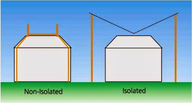
When designing the external lightning protection system of a structure, we distinguish between two types of air-termination system (see Fig.2):


  1. Non-isolated system,
  2. Isolated system.


Fig.2: Air Termination System Types


1- Non-Isolated System:

  • Where potentially damaging voltage differentials are limited by bonding the lightning protection system to the structure.


2- Isolated System:

  • Where the lightning protection system is isolated from the structure by a specified separation distance. This distance should be sufficient that energy is contained on the LPS and does not spark to the structure.
  • Isolated systems are well suited to structures with combustible materials such as thatched roofs, or telecommunication sites that want to avoid lightning currents being conducted on masts and antenna bodies.
  •  The isolated system uses Catenary (or suspended) conductors. One or more catenary conductors may be utilized to provide a zone of protection over an entire structure.


Forms of Strike Termination Subsystem

The strike termination subsystem can take many forms specified by the various engineering standards available (see Fig.3), as follows:

  1. Vertical Air Terminals,
  2. Horizontal air termination network,
  3. Combination of Vertical Air Terminals and Horizontal air termination network,
  4. Natural Air Terminals.


 Fig.3: Forms of Strike Termination Subsystem


1- Vertical Air Terminals:


  • The air terminal is a metal device listed for the purpose by a Nationally Recognized Testing Laboratory like UL, and is connected in an electrically and mechanically robust fashion to the conductor subsystem. In general, it is consisting of a metal rod protruding above a structure.
  • Vertical Air Terminals may be used as free standing masts or linked with conductors to form a mesh on the roof. They are commonly known as lightning rods or Air Rods or Air Finals.


2- Horizontal air termination network:

The horizontal air termination networks have (2) method of installation:

  • Meshed conductor network,
  • Overhead wires (Catenary wires).


A- Meshed conductor network:


- Meshed conductor network is installed by (2) ways:

  • It may lie in direct contact with the roof in order to reduce the effect of flashover caused by a large induction loops,
  • It may be suspended above it in the event that it is of paramount importance that the roof is not exposed to a direct lightning discharge.


- Meshed conductor network usually uses bare copper strip (25×3 mm for example) which will be supported at equal intervals.

- Meshed conductor network can be applied in two sizes:
 (5 m X 10 m) mesh,
 (10 m X 20 m) mesh.
The first one is used in high risk structure such as explosives factors.


B- Overhead wires (Catenary wires):


One or more catenary conductors may be utilized to provide a zone of protection over an entire structure. Catenary (or suspended) conductors, whether they are supported by free standing masts or linked with conductors to form a mesh on the roof.


3- Combination of Vertical Air Terminals and Horizontal air termination network


that is used in important buildings for increasing the protection against Lightning strikes, where Vertical Air Terminals and Horizontal air termination can combined together to consist one Air Termination System.


4- Natural Air Terminals:

  • When metallic roofs are being considered as a natural air termination arrangement, then BS 6651 gives guidance on the minimum thickness and type of material under consideration. BS EN 62305-3 gives similar guidance as well as additional information if the roof has to be considered puncture proof from a lightning discharge. See Table in Fig.4, which provides the thickness requirements for natural air termination.


Fig.4: the Thickness Requirements for Natural Air Termination

  • The requirements for natural air-terminations are:

  1. To withstand the ohmic heating and electromechanical/magnetic forces,
  2. To withstand the heat of the lightning plasma arc.


  • Metal pipes and tanks on roofs can be used, provided they meet the requirements of Tables in Fig.4 and Fig.5


Fig.5: Minimum Material Dimensions for Natural Air Termination


Notes:

  • For Table in fig.4, Where combustible materials are not present, and water ingress can be tolerated from a puncture due to lightning, then thinner material is permitted for air-terminations.
  • If the materials do not meet these requirements in Fig.4 and Fig.5, then they must be protected by the lightning protection system.
  • It is not desirable to use vessels and pipe work which contains gas or liquids under high pressure or flammable gas or liquids.


In the next Article, I will continue explaining the Conventional Lightning Protection System LPS Components. Please, keep following.


No comments:

Post a Comment