Conventional Lightning Protection System Components – Part Three


In Article   Introduction to Lightning System Design- Part One ", I listed all terms, abbreviations and Symbols used in lightning field.

Also, in Article 
Introduction to Lightning System Design- Part Two ", I answered the following questions:
  • What is Lightning? 
  • What are the types of Lightning flashes?
  • What is the shape of The Lightning Waveform?
  • How Lightning strikes can affect the electrical and/or electronic systems of a building?
  • What are the main effects of Lightning?

And in Article 
Types Of Lightning Protection Systems LPS ", I list the main types of Lightning Protection Systems as follows:


Types of Lightning Protection Systems LPS


Types of Lightning Protection Systems LPS

Lightning protection systems for buildings and installations may be divided into three principal types as follows:

1- LPS for Protection for buildings and installations against direct strike by lightning, which includes:

A- Conventional lightning protection system, which includes:

  1. Franklin Rod LPS,
  2. Franklin/Faraday Cage LPS.


B- Non-Conventional lightning protection system, which includes:

a- Active Attraction LPS, which includes:

  1. Improved single mast system (Blunt Ended Rods),
  2. Early streamer Emission System.


b- Active Prevention/Elimination LPS, which includes:

  1. Charge Transfer System (CTS),
  2. Dissipation Array System (DAS).


2- LPS for Protection against overvoltage on incoming conductors and conductor systems,

3- LPS for Protection against the electromagnetic pulse of the lightning.


Notes on different Types of Lightning Protection Systems LPS

Each system’s design requires the following:

  1. The air terminal or strike termination device must be positioned so that it is the highest point on the structure.
  2. The lightning protection system must be solidly and permanently grounded. Poor or high resistance connections to ground are the leading cause of lightning system failure for each one of these systems.
  3. None of these systems claims to protect against 100% of the possibility of a lightning stroke arriving near protective area. A compromise must be made between protection and economics.


And in Article " Conventional Lightning Protection System Components – Part One ", I indicated the Conventional Lightning Protection System parts and components as follows:


Conventional Lightning Protection System LPS Components

The Conventional Lightning Protection System consists of two main parts:

1- The External Lightning Protection System, which includes:

  • Strike Termination Subsystem,
  • Conductor Subsystem,
  • Grounding Electrode Subsystem.


2- The Internal Lightning Protection System, which includes:

  • Equipotential Bonding Subsystem,
  • Surge Protection Subsystem.


Another important components of the Lightning Protection System is the Connection Components which include but not limited to:

  • Clamps,
  • Connectors,
  • Terminal components,
  • Bridging components,
  • Expansion pieces,
  • Measuring points.


And I explained the Strike Termination Subsystem in this Article.

Also, in Article " Conventional Lightning Protection System Components – Part Two ", I began explaining the Conductor Subsystem through the following points:

  • Function of Conductor Subsystems,
  • Effects of Lightning Strikes on Conductor Subsystems,
  • Conductor Subsystem Material Requirements.


Today, I will continue explaining the Conductor Subsystem through the following points:

  • Types of Lightning Conductors,
  • Installation Requirements For Down Conductors.


Conductor Subsystem -Continued


1- The Correct Choice Of Lightning Protection Components (LPC)


  • The correct choice of material, configuration and dimensions of the lightning protection components is essential when linking the various elements of an LPS together. 
  • The designer/user needs to know that the components, conductors, earth electrodes etc will meet the highest levels when it comes to durability, long term exposure to the environmental elements and perhaps most importantly of all, the ability to dissipate the lightning current safely and harmlessly to earth.
  • Various standards series have been compiled with this very much in mind. At present these standards are as follows:


Standards for Lightning Protection Systems


1- Within Europe:

Various standards series have been issued by (2) National Committees which are:

  1. The European Committee for Electrotechnical Standardisation (CENELEC).
  2. The International Electrotechnical Commission (IEC)


The CENELEC has released the EN 50164 series of standards. The EN 50164 series are component standards to which the manufacturers and suppliers of lightning protection components should test their products to verify design and quality. The EN 50164 series currently comprises of:

  • EN 50164-1 Lightning protection components (LPC) – Part 1: Requirements for connection components,
  • EN 50164-2 Lightning protection components (LPC) – Part 2: Requirements for conductors and earth electrodes,
  • EN 50164-3 Lightning protection components (LPC) – Part 3: Requirements for isolating spark gaps,
  • EN 50164-4: Lightning Protection Components (LPC) – Part 4: Requirements for conductor fasteners,
  • EN 50164-5: Lightning Protection Components (LPC) – Part 5: Requirements for earth electrode inspection housings and earth electrode seals,
  • EN 50164-6: Lightning Protection Components (LPC) – Part 6: Requirements for lightning strike counters,
  • EN 50164-7: Lightning Protection Components (LPC) – Part 7: Requirements for earthing enhancing compounds.


Notes:

  • The standards generally have an IEC prefix to their number (CEI for French versions). IEC standards are produced in English and French languages.
  • IEC and CENELEC generally work in parallel, and CENELEC members vote to adopt new IEC standards as CENELEC standards. The committees of CENELEC may choose to make some alterations to the IEC version.
  • Additionally, CENELEC produce their own standards to which IEC have no counterpart. CENELEC documents are produced in English, French and German and an approved CENELEC standard will have an EN prefix (or NE in the French language versions).


For example:

IEC 62305-1 (IEC version) is parallel to EN 62305-1 (CENELEC adopted copy of the above)
And both are parallel to BS EN 62305-1 (British National Standard adoption ofthe above)


2- Within USA:

Various standards series have been issued such as:

  1. Underwriters Laboratory (UL96 & 96A),
  2. The National Fire Protection Association (NFPA 780)
  3. The Lightning Protection Institute (LPI-175)


Note:

For heavy fault conditions, Conductor Size should be calculated in accordance with IEEE Std 80.


2- Types of the Conductors in Conductor Subsystems

The Conductor Subsystem is consisting of two types of conductors as follows:

  1. The Air-Termination Conductor (the Main Conductor),
  2. Down Conductor (The Extension Conductors).


Note:

It is possible that the same conductor type may be used for:

  • Air-Terminations (e.g. mesh method),
  • Down-Conductor, 
  • Earthing Electrodes (counterpoise ring).


2.1 The Air-Termination Conductors (The Main Conductors)

The Air-Termination Conductors is the electrically conductive connection between the air-termination system and the down conductors.


2.2 Down Conductors (The Extension Conductors)

  • The down-conductor is the electrically conductive connection between the main conductors and the earth-termination system.
  • It is an extension or a direct continuation of the main conductor and it is the path to the ground for the lightning stroke current that is captured by air terminals.

  • Down conductors installation criteria differs according to Type of Lightning Protection System:

  • Down-Conductors for Non-Isolated LPS,
  • Down-Conductors for Isolated LPS.


 Isolated and Non-Isolated LPS


2.2.A Down-Conductors for a Non-Isolated Lightning Protection System

In non-isolated lightning protection system, the down-conductors are primarily mounted directly onto the structure (with no distance).

But, sometimes a separation distance is required between the down conductors and the structure. This is governed by the criteria of temperature rise in the event of lightning striking the lightning protection system.

Temperature Rise Criteria:

The temperature rise criterion is based on the level of flammability for the structure walls; we have two cases as follows:

Case#1: If the wall is made of flame-resistant material or material with a normal level of flammability

In this case, the down-conductor systems may be installed directly on or in the wall.

For example, Wood with a bulk density greater than 400 kg/m2 and a thickness greater than 2 mm is considered to have a normal level of flammability. Hence the down-conductor system can be mounted on wooden poles.

Case#2: If the wall is made of highly flammable material

In this case, we have two sub-cases according to considering the temperature rise (when lightning currents flow) is a hazard or not, this is can be known from table as follows:

the below Table states the maximum temperature rise ΔT in K of the various conductors for each class of lightning protection system. These values mean that, generally, it is even permissible to install down conductors underneath heat insulation because these temperature rises present no fire risk to the insulation materials. This ensures that the fire retardation measure is also provided.


So, the two sub-cases for case#2: If the wall is made of highly flammable material, are:


Case#2-A: The temperature rise of the down-conductor systems is not hazardous

In this case, the down conductors can be installed directly on the surface of the wall.


Case#2-B:  The temperature rise of the down-conductor systems presents a hazard

In this case, the down conductors must be mounted (by using Standoff brackets for example)(see fig.1) to ensure that the separation distance between the down-conductor and the wall is greater than 0.1 m. The mounting elements may touch the wall.


fig.1: Standoff brackets


Notes:

  • When installing the down-conductor system in or underneath heat insulation, the temperature rise (on the surface) is reduced if an additional PVC sheath is used. Aluminum wire sheathed in PVC can also be used.
  • The erector of the structure must state whether the wall, where a down-conductor is to be installed, is made of flammable material.


2.2.A.1 Requirements of Down Conductor Installation In Non-Isolated Lighting Protection System

The following requirements for Down Conductor Installation in Non-Isolated Lighting Protection System must be considered:

  • Down conductors must not be sited in gutters or down pipes even if they are insulated due to the risk of corrosion occurring.
  • Down conductors must be fitted with external protection to reduce exposure to accidental damage or vandalism (see fig.2), The bottom 3 meters of the down conductor should be protected within a metal guard or PVC or cross-linked polyethylene covering at least 3 mm thick where there is risk of danger due to touch potential and to deter vandalism and theft.


 fig.2: External Protection

  • It is recommended to mount down conductors to maintain the required separation distance s to all doors, windows and exits or where people may congregate.
  • Metal gutters must be connected with the down conductors at the points where they intersect (see fig.3).

fig.3

  • The base of metal downpipes must be connected to the equipotential bonding or the earth-termination system, even if the pipe is not used as a down conductor. Since it is connected to the eaves gutter, through which the lightning current flows, the downpipe also takes a part of the lightning current which must be conducted into the earth termination system (see fig.3).
  • Sometimes it is not possible to install down conductors down a particular side of a building due to practical or architectural constraints. On these occasions more down conductors at closer spacings on those sides that are accessible should be installed as a compensating factor.


2.2.B Down conductors of an isolated external lightning protection system

The general requirements for down-conductors in an isolated LPS are:

  • If an air-termination system comprises air-termination rods on isolated masts (or one mast), then this is both air-termination system and down-conductor system at the same time (see Fig.4).

Fig.4

  • Each individual mast requires at least one down conductor.
  • Steel masts or mast with an interconnected steel reinforcement require no supplementary down-conductor system. a metal flag pole, for example can also be used as an air-termination system.
  • The separation distance s between the air-termination and down-conductor systems and the structure must be maintained.
  • If the air-termination system consists of one or more spanned wires or cables (like catenary wires), each end of the cable which the conductors are attached to requires at least one down conductor (see Fig.5).

Fig.5

  • If the air-termination system forms an intermeshed network of conductors, i.e. the individual spanned wires or cables are interconnected to form a mesh (being cross-linked), there must be at least one down conductor at the end of each cable the conductors are attached to (see Fig.6).

Fig.6


3- Installation Requirements For Down Conductors


3.1 General Consideration For Down Conductors Installation

To avoid damage caused during the lightning current discharge to the earth-termination system such as side flash which depends on inductance value of the down conductors. The following requirements must be considered:

  • Increasing the number of parallel down conductors, since, the lightning current is shared between the down conductors, the greater the number of down conductors, the lesser the current that flows down each. This is enhanced further by equipotential bonding to the conductive parts of the structure.
  • There should always be a minimum of two down conductors distributed around the perimeter of the structure.
  • Down-conductors should be equally distributed around the perimeter of the structure (within practical and aesthetic reasons).
  • Reducing the lengths of down conductors to avoid loops i.e. down conductors must be straight, vertical and with no loops. If this can’t be achieved another design for the down conductor system should considered.
  • The down conductor route(s) should be as direct as possible with no sharp bends or stress points where the inductance, and hence impedance, is increased under impulse conditions. (Note that Sharp 90° bends will make the lightning jumps off the end of the wire and back on several inches down).
  • The connections to conductive components of the structure (equipotential bonding) are made wherever required.
  • By interconnecting the down conductors at ground level (base conductor) and using ring conductors for higher structures, it is possible to balance the distribution of the lightning current by improving current sharing between down-conductors.
  • Down conductors should wherever possible (within 300 mm) be installed at each exposed corner of the structure as research has shown these to carry the major part of the lightning current.
  • To reduce touch and step potential hazards, select routes where any external earth electrode systems would need to be located in a similar location.


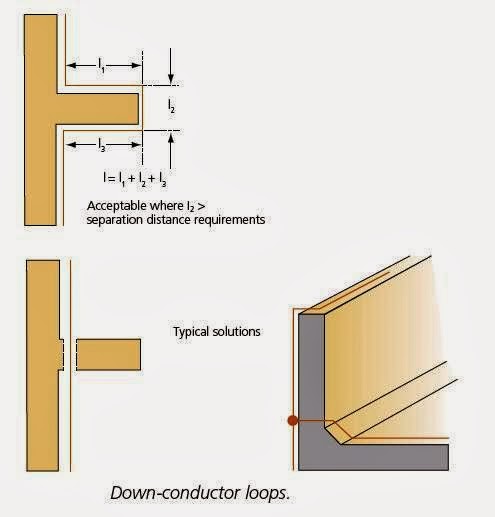
3.2 Down Conductor Routing

The criterion for the best routing of down conductors is as follows:

  • Down-conductors should, where possible, be installed straight and vertical, but generally following the profile of the building.
  • Loops and overhangs should be avoided. Where loops cannot be avoided, the distance s, across the gap shall be greater than the separation distance for length l (see fig.7). If this is not possible then the down-conductor should be routed directly through the structure.


Fig.7: Down Conductor Loops and Solutions


We have many cases where special solutions must be provided for correct routing of down conductors as follows:


1- Structures with overhangs

  • Structures with overhangs where the down-conductor must be routed along the overhang can create a hazardous risk of flashover. This is of particular concern where persons can be present. This situation should be avoided if the required separation distance (to a person with outstretched arms (2.5 m) cannot be maintained (see fig.8).

Fig.8

  • Additional down conductors may be required to meet the separation requirements, or locate down conductors in air space of non-metallic, non-combustible internal duct (not containing electrical cables).
  • To reduce the risk of the person becoming an alternative path for the lightning current to that of the external down conductors, then the following condition should be satisfied (see fig.9):


Fig.9


h>2.5+ s

Where:

h = Height of the overhang (in meters),
s = Required separation distance calculated in accordance with Section 6.3 of BS EN 62305-3.


2- Routing Down Conductors within Walls, Or the Wall Cavity

Care is required in routing conductors within walls, or the wall cavity:

  • Open cavities are preferred as the thermal expansion of the down-conductor under lightning conditions can cause cracking of plaster covered conductors.
  • Bare aluminum conductors should not be placed in direct contact with plaster, mortar or concrete, etc.
  • Discoloration of plaster should be considered.
  • In areas with limited volume or strength, the electromechanical shock wave may cause damage.


3- Large Flat Structures

  • If the edges of the structure (length and width) are four times as large as the distance of the down conductors which corresponds to the class of lightning protection system, then supplementary internal down conductors must be installed (see fig.10).


Fig.10

  • In large flat structures, such as large production halls or also distribution centers, where more than 4 down-conductors are required on one of the perimeter surfaces (e.g. industrial buildings, exhibition halls, etc), then extra internal down conductors should be installed approximately every 40 m i.e. The grid dimension for the internal down-conductor systems is around 40 m x 40 m. Roof support columns should be utilized.


4- Courtyards

Structures with enclosed courtyards having a perimeter greater than 30 m (see fig) must have down-conductor systems installed with the distances (see fig.11).


Fig.11


3.3 Fixing Of Down Conductors

Fixing centers for the air termination and down conductors are shown in below Table:


3.4 Measuring Points (Test Joints)


Each down conductor will be provided with a test joint designed and situated to:
  1. Provide access for resistance or continuity measurements to be made,
  2. Enable disconnection from the earth network.


Fig.12: Test Joints


Notes:

  • Test joints will be positioned where are easily accessible and convenient for the tests.
  • The height of the test joints will be 2.0m above grade level.
  • The measuring point may only be opened with the help of a tool for the purpose of taking measurements, otherwise it must be closed.
  • Each measuring point must be able to be clearly assigned to the design of the lightning protection system. Generally, all measuring points are marked with numbers (see fig.12).
  • No test joints are used where natural down conductors are combined with foundation earthing.


In the next Article, I will explain How to use Natural Structure Components as down Conductors. Please, keep following.


No comments:

Post a Comment