
Also, In Article " Conductor Ampacity Calculation – Part Nine ", I explained how to use the Tables included under Group#1 which were:
- TABLE B.310.15(B)(2)(1),
- TABLE B.310.15(B)(2)(3).
Today, I will explain how to use Other Annex B tables and figures.
For more information about the first method for Conductors ampacity calculations by using Tables as provided in 310.15(B), please review the following articles:
Using Annex B tables and figures
Rule#1: Annex B Tables And
Figures
Annex B consists of
many tables and figures as follows:
Tables:
Figures:
The following
figures represent Underground electrical duct bank configurations:
|
To download a PDF copy of Annex B tables and figures, click on the link.
The above tables can be divided to groups as follows:
- Tables Group#1: tables for conductors installed in free air.
- Tables Group#2: tables for conductors installed in underground electrical duct bank tables.
- Tables Group#3: adjustment factor tables
The above figures can be divided to groups as follows
- Figures Group#1: adjustment figure for Thermal Resistivity and Load Factor.
- Figures Group#2: special case figures.
Second: Tables Group#2: tables for conductors installed in underground electrical duct bank or directly Buried tables.
This tables group can be divided to two sub-groups as follows:
1- Tables Group#2-A: tables for conductors installed in underground electrical duct bank which includes:
- TABLE B.310.15(B)(2)(5) in Accordance with Figure B.310.15(B)(2)(2),
- TABLE B.310.15(B)(2)(6) in Accordance with Figure B.310.15(B)(2)(2),
- TABLE B.310.15(B)(2)(7) in Accordance with Figure B.310.15(B)(2)(2),
2- Tables Sup-Group#2-B: tables for conductors directly Buried in earth which includes:
- TABLE B.310.15(B)(2)(8) in Accordance with Figure B.310.15(B)(2)(2),
- TABLE B.310.15(B)(2)(9) in Accordance with Figure B.310.15(B)(2)(2),
- TABLE B.310.15(B)(2)(10) in Accordance with Figure B.310.15(B)(2)(2),
1.1 Tables Group#2-A Construction


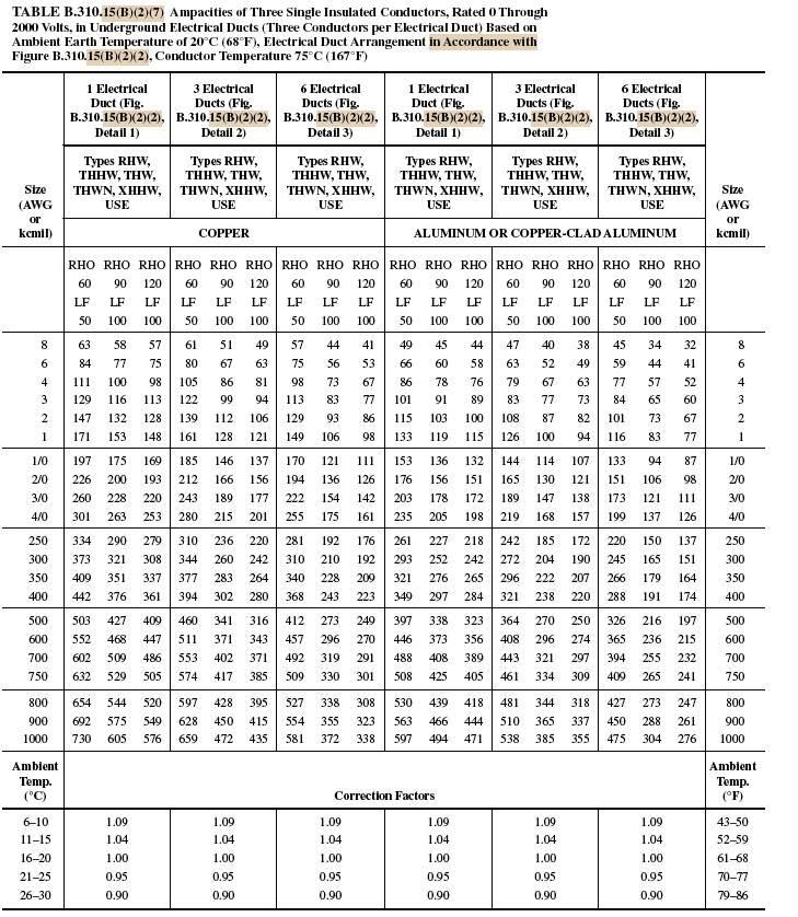
For example, TABLE B.310.15(B)(2)(5) Ampacities of Single Insulated Conductors, Rated 0 through 2000 Volts, in Nonmagnetic Underground Electrical Ducts (One Conductor per Electrical Duct), Based on Ambient Earth Temperature of 20°C (68°F), Electrical Duct Arrangement in Accordance with Figure B.310.15(B)(2)(2), Conductor Temperature 75°C (167°F).
 |
Fig(1) |
Table B.310.15(B)(2)(5) consists of: (see fig.1)
1.1.A Conditions for table application
These conditions are existing in the table description at the top of the table, and in table B.310.15(B)(2)(5) , these conditions are:
|
1.1.B Conductor Material Sections
Two main Sections for
conductor material type are existing:
|
1.1.C Electrical Duct Configurations
Each of The two main sections
for conductor material types is divided into three electrical Duct
Configurations:
Noting that:
|
1.1.D Conductor Sizes Columns
Two Columns for conductor
sizes range from 250 to 2,000 kcmil:
|
1.1.E Correction Factors for Ambient Temperature
Under each main Material
Section; copper and aluminum/copper-clad aluminum conductors, there is a
section of Correction Factors for Ambient Temperature
Which gives the value of a
correction factor for Ambient Temperature based on the Actual Ambient
temperature columns in the right and left of this section.
|
Other tables included in Group#2-A have the same construction as explained above for table B.310.15(B)(2)(5) but of course they will differ as per the following table:
Table B.310.15(B)(2)(5)
|
Table B.310.15(B)(2)(6)
|
Table B.310.15(B)(2)(7)
|
|
Conditions for table
application (see fig.2)
|
Single Insulated
Conductors in Nonmagnetic Underground
Electrical Ducts (One Conductor per Electrical Duct),
|
Three Insulated
Conductors Within an Overall Covering (Three-Conductor Cable) in Underground
Electrical Ducts (One Cable
per Electrical Duct)
|
Three Single
Insulated Conductors in Underground Electrical Ducts (Three Conductors per
Electrical Duct)
|
Number of Electrical Ducts
|
3,6
and 9
|
1,3
and 6
|
1,3
and 6
|
Allowable Electrical Duct Configurations (see fig.3)
|
Detail 2 ,3 and 4
|
Detail 1 ,2 and 3
|
Detail 1 ,2 and 3
|
Allowable Conductor Sizes
|
from
250 to 2,000 kcmil
|
from
8 AWG to 1,000 kcmil
|
from
8 AWG to 1,000 kcmil
|
 |
| Fig(2) |
 |
| Fig(3) |
1.2 Notes for Tables Group#2-A:
Note#1
All tables included under
group#2-A are used in Accordance with electrical duct bank configurations
included in Figure B.310.15(B)(2)(2) (see fig.3)
|
Note#2
Only the conductors/cables
with the following insulation materials are used under tables of group#2-A:
Types RHW, THHW, THW, THWN,
XHHW, USE.
Don’t apply tables group#2-A
for conductors/cables with other insulation materials listed above.
|
Note#3
Apply Ambient temperature
correction factors if the actual earth ambient temperature not 20°C (68°F)
and as per the Correction Factors section included if each table of group#2-A
|
Note#4
Minimum burial depths to top
electrical ducts or cables shall be in accordance with 300.5. Maximum depth
to the top of electrical duct banks shall be 750 mm (30 in.) and maximum
depth to the top of direct buried cables shall be 900 mm (36 in.)
|
Note#5
For two and four electrical
duct installations with electrical ducts installed in a single row, see
B.310.15(B)(5).
|
Note#6
All three tables included in
group#2-A have same values of thermal resistivity (RHO) and Load Factor (LF) which
are as follows:
But if in some installations
we have different values of thermal resistivity (RHO) and Load Factor (LF),
what will be done?
The answer is using Figure
B.310.15(B)(2)(1) in below image, which make Interpolation for the values of
current ampacity for these installations based on two known ampacities for
standard values of thermal resistivity (RHO) and Load Factor (LF). (this will
be explained in detail in next Articles)
|

1.3 How to use these Tables group#2-A
Step#1: Determine the proper table to use based on the existing wiring method conditions
For example, if we have Three Insulated Conductors 2 AWG Copper , THHW Within an Overall Covering (Three-Conductor Cable) in Underground Electrical Ducts (One Cable per Electrical Duct) based on an earth ambient temperature of 30° C (86° F), which table we will use; Table B.310.15(B)(2)(5) or Table B.310.15(B)(2)(6) or Table B.310.15(B)(2)(7)?

- Yes, it is table B.310.15(B)(2)(6),
- why it is not Table B.310.15(B)(2)(5) because we have three Insulated Conductors not single one,
- why it is not Table B.310.15(B)(2)(7) because we have Three Insulated Conductors Within an Overall Covering (Three-Conductor Cable) not Three single Insulated Conductors.

Step#2: Determine the proper section in the selected table based on the conductor material type (Copper – Aluminum or Copper Clad Aluminum)
In same example above, because this is a copper conductor, we will use the section in the left side of table B.310.15(B)(2)(6).
Step#3: Reading the Ampacity Value (Given RHO = 90 and LF=100, Detail #2)
In the table section selected above, move down to the given conductor size, which is 2 AWG in our example, the amapcity value are existing in the 2 AWG Row.
Now, move to the right in the 6AWG row until you reach the column for detail#2 configuration and for RHO = 90 and LF=100 a the reading will be in this column.
Step#4: Now read the amapcity of the conductor, you should read 105.
In the next Article, I will explain how to use Other Annex B tables and figures groups. Please, keep following.

No comments:
Post a Comment