
I explained how to insert Luminaires in the outdoor Area by using Visual professional edition software in previous Article " Visual Software for Outdoor Lighting Design – Part Four ".
Today, I will explain Other Steps for Inserting Calculation Planes and Performing the Calculations as follows.
You can review the following previous articles for more information and good following:
Step#9: Inserting Calculation Planes
In this step, we will learn how to:
- Insert a Vertically Oriented Calculation Plane.
- Insert a Horizontal Calculation Plane.
- Remove Unwanted Calculation Points.
1- Inserting a Vertically Oriented Calculation Plane
We need to put calculation points on the wall that we just lit by doing the following:
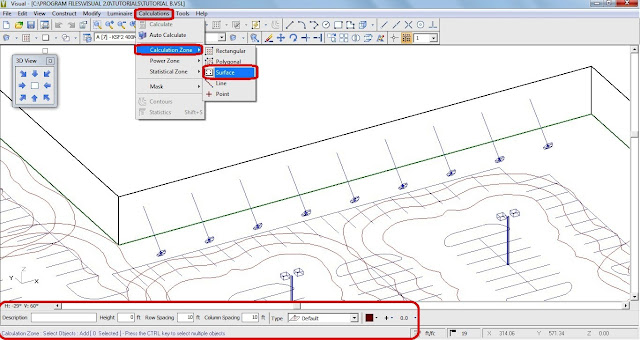
- From the menu, select CALCULATIONS, CALCULATION ZONE, SURFACE. The Status Bar will prompt you to select objects.
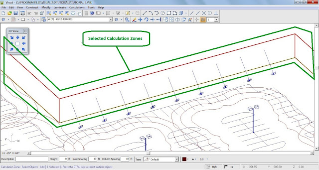
- Left-Click on the line that defines the top of the wall. You will see that two surfaces (the desired wall and the roof) have been selected as in the image below.
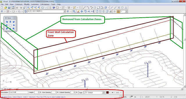
The selection process allows objects to be removed from the selection set. To toggle to the “Remove” selection mode, press the R key on the keyboard. The Status Bar will indicate that the subsequently selected items will be removed from the current selection set. (The A key toggles back to "Add" mode)
- Left-Click the roof on a line that it does not share with the wall. This will remove it from the selection set.
- The Property Bar will prompt for a description, a height, row and column spacings, normal orientation, and color. Enter the settings shown below.
- Right-Click the mouse in the Design Window to terminate the command. The calculation zone will be added to the wall.
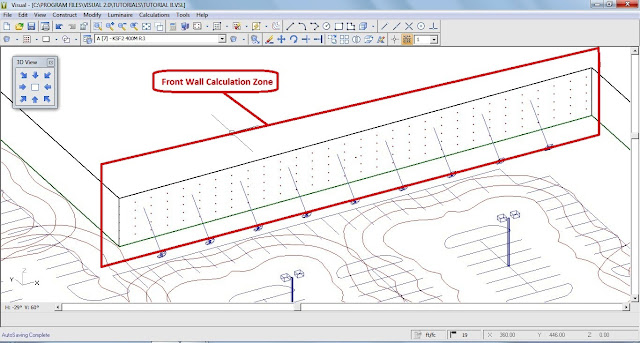
You should verify that the calculation plane was placed on the surface correctly.
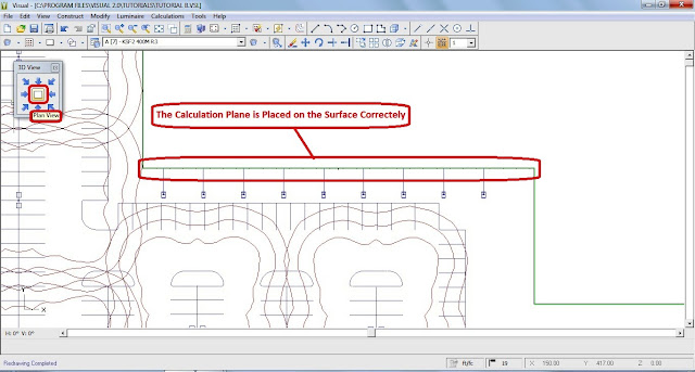
- Left-Click the PLAN VIEW button on the 3-D VIEW TOOLBAR. The Design Environment should look like the graphic below (i.e. the calculation plane is coincident with the surface). If not, you should select UNDO from the EDIT MENU and repeat the above process.
2- Inserting a Horizontal Calculation Plane
You are now going to place a horizontal calculation plane at grade over the parking areas only.
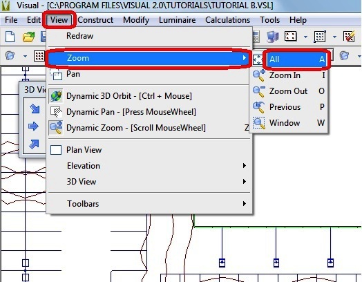
- View the entire lighting model by selecting ZOOM, ALL from the VIEW MENU.
- Press the HOME key on the keyboard to ensure that the working plane is set to the X-Y plane (Z = 0).
- From the menu, select CALCULATIONS, CALCULATION ZONE, RECTANGULAR. The Status Bar will prompt for coordinate selection. The Property Bar will prompt for a description, a height, and row and column spacings for the calculation points as shown below.

- Enter the Description by placing the mouse cursor in the text box and typing. The Height should 0. The Row and Column Spacing should be set to 20.
- Right-Click on the Design Window to indicate that you are finished editing and ready to enter coordinate information. The mouse pointer will change to crosshairs.
- Using the mouse, position the crosshairs at (85,155,0) and Left-Click to pick the first corner of the calculation plane. (It is also possible to type the coordinates on the keyboard by entering “85 <space> 155 <space> 0”.)
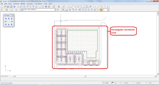
- Pick a point with the crosshairs (by Left-Clicking the mouse) that is slightly beyond the back of the structure in the upper right-hand corner to completely cover the parking area with the calculation plane. Coordinates of (740,740,0) are recommended (It is also possible to type the coordinates on the keyboard by entering “740 <space> 740 <space> 0”.).
3- Removing Unwanted Calculation Points
By examining the lighting model, you will see that there are calculation points inside the structure which need to be removed, as well as extraneous points around the boundary of the parking area.
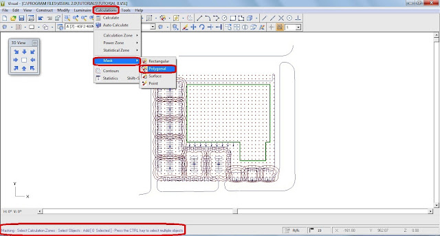
- From the CALCULATIONS MENU, select MASK, POLYGONAL. The Status Bar will prompt for the selection of the Calculation Zone that you wish to mask. Select the parking lot Calculation Zone that you just constructed. Right-Click the mouse to indicate that you finish selecting the Calculation Zone.
- The Status Bar will now prompt for entry or selection of the first vertex of a polygonal shape that will define the mask.
- Left-Click the mouse on first Vertex and follow clicking other vertices till you complete the polygon.
- Right-Click the mouse to indicate that all of the vertices have been selected and complete the command. The final side of the polygon will automatically be drawn to close the polygonal exclusion area and remove the unwanted points. The mask will be displayed by a dashed purple polygon.
- Repeat the mask command as necessary until all unwanted points have been masked.
Your screen should look similar to the image below.

Step# 10: Performing Calculations and Viewing Results
The model is now complete and ready for analysis.
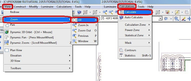
- Select ZOOM, ALL from the VIEW MENU.
- Select CALCULATE from the CALCULATIONS MENU. Visual will analyze the lighting model. The Status Line will report the different calculations being performed and a blue progress indicator will appear on the Status Bar to inform you of the progress of each calculation.

- When Visual is finished, the calculation points will display their associated numerical illuminance values.
- Select STATISTICS from the CALCULATIONS MENU. The Statistics Window will appear and report the statistical results for the two defined calculation planes.
- Select Southwest view from the 3-D VIEW TOOLBAR to see both calculation zones.
The screen should look like the image below.
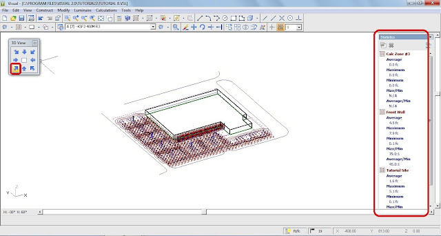
Notes:
- the maximum values printed in bright red and the minimum values printed in blue.
- The density of points may make it difficult to read individual values.
- From the VIEW MENU, select ZOOM…WINDOW to view any areas of interest.
Panning is used to shift the contents of the Design Window in order to reveal portions of the model space adjacent to the current view.
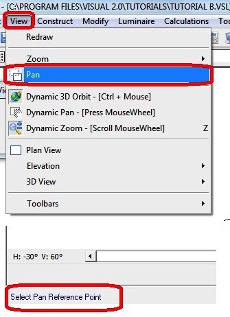
- Select PAN from the VIEW MENU to translate the view of the model and evaluate the various illuminance values. The Status Bar will prompt for a reference point (base point).
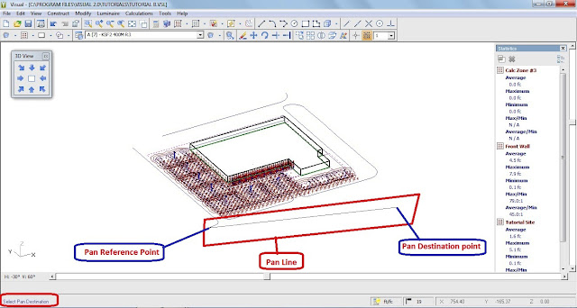
- Left-Click the mouse in the Design Window at a point which is on the left-hand side of the screen. The Status Bar will now prompt for the destination point where this point is to be moved.
- Left-Click the mouse at a point on the right-hand side of the screen. Visual will then translate the contents of the Design Window based on the points selected.
You are now ready to print the results if desired.
In the next Article, I will explain Last Step# 11: how to print the results for Visual Lighting software. Please, keep following.
In the next Article, I will explain Last Step# 11: how to print the results for Visual Lighting software. Please, keep following.
3RT5QY4V42SU

Is amazing software ever..
ReplyDelete