
I explained how to start a new design for outdoor lighting by using Visual professional edition software in previous Article " Visual Software for Outdoor Lighting Design – Part Three ".
Today, I will explain step#8: how to insert Luminaires in the outdoor Area as follows.
You can review the following previous articles for more information and good following:
Step#8: Inserting Luminaires
This step can be divided into sub-steps as follows:
A- preparation of Design Environment
Note: Upon returning to the Design Environment, you will note that the Luminaire Toolbar is populated with the objects from the Luminaire schedule. The drop-down list box is used to select a Luminaire for placement.
B- Placing of Luminaires
- preparation of Design Environment
- Placing of Luminaires
- Inserting Luminaires using "Place and Orient"
- Inserting Luminaires using "Place & Aim"
A- preparation of Design Environment
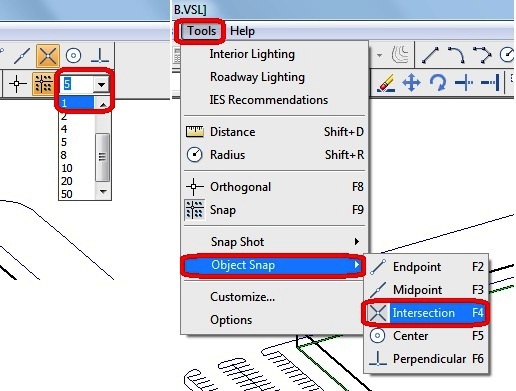
- Left-click the mouse on the down arrow on the right side of the Snap Increment Combo Box and select a value of “1”.
- Turn on the Intersect Object Snap from the TOOLS, OBJECT SNAP MENU.
Note: Upon returning to the Design Environment, you will note that the Luminaire Toolbar is populated with the objects from the Luminaire schedule. The drop-down list box is used to select a Luminaire for placement.
B- Placing of Luminaires

- Left-Click the drop-down arrow at the right side of the Luminaire list box and select Luminaire Type A (KSF2 400M R3) from the list.
- Select PLACE from the LUMINAIRE MENU. The Status Bar will prompt for coordinate selection.
- The Property Bar will display edit boxes for Mounting Height, Orientation, and Tilt as shown below in above image.
- An implied Luminaire symbol graphic will be attached to the mouse crosshairs.
- The Mounting Height field corresponds to the height at which the Luminaires will be placed above the current working plane.
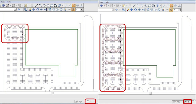
The templates are used to determine the initial placement and proper spacing of the luminaires. For reference, the first luminaire should have coordinates of approximately (153,655,0), and the luminaires should be approximately 108 feet apart along the Y-Axis. It is good practice to locate poles in parking lots at the intersection(s) of the parking lot lines in order to make parking the automobiles easier. The Intersect Object Snap aids in this task.
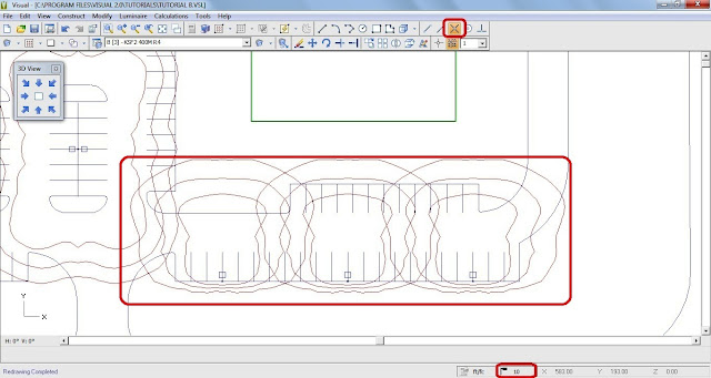
- Insert five Type A Luminaires as shown in the image below.
C- Place and Orient of Luminaires
1- (A) luminaire
This step is to place two additional Type A Luminaires using a similar process.
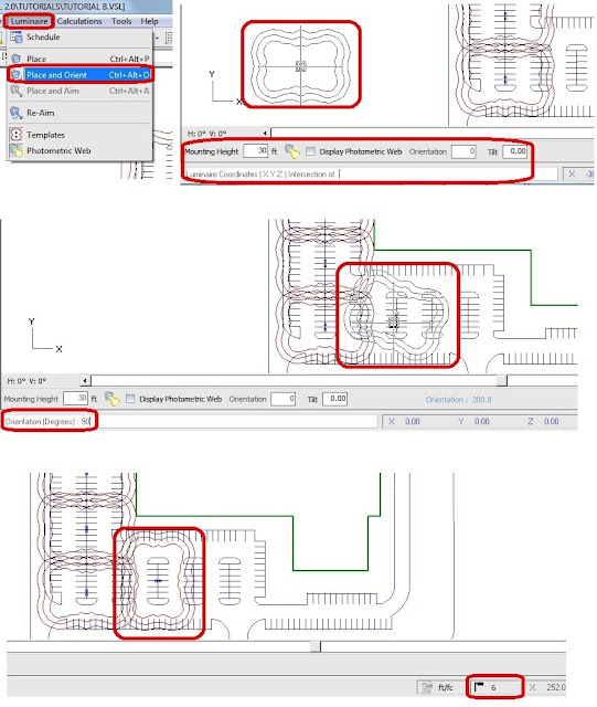
- Select PLACE & ORIENT from the LUMINAIRE MENU.
Notes:
- The Status Bar will prompt for coordinate selection.
- The Property Bar will again display edit boxes for Mounting Height, Orientation, and Tilt. No editing of these values is necessary.
- An implied Luminaire symbol graphic will be attached to the mouse crosshairs.
Used Criteria: (see above image)
- The Place & Orient method allows the Luminaire orientation to be specified graphically. After the Luminaire location is selected by Left-Clicking the mouse at the desired location, an additional coordinate must be entered to define the rotational orientation of the Luminaire.
- Luminaire orientation is graphically depicted as the mouse crosshairs are moved within the Design Window. This additional coordinate can be entered by Left-Clicking the mouse when the desired orientation is shown by the implied image, or a value can be entered by typing on the keyboard.
- Left-Click the mouse at a location close to (288,247,0). The Luminaire will be sited, and the Status Bar will now provide the current Orientation of the Luminaire in blue text toward the right side of the screen.
- Type 90 into the Command Line and press the ENTER key. This will complete the placement of this Luminaire, and a new luminaire will be ready to place and orient.
- Right Click in the Design Window to terminate the Place and Orient command.
After placing the two additional Type A Luminaires, the screen should look like the image below.
2- (B) Luminaires
You will notice that a small portion of the parking remains unaddressed.
- Left-Click the drop-down arrow at the right side of the Luminaire list box and select Luminaire Type B (KSF2 400M R4) from the list.
- Select PLACE from the LUMINAIRE MENU.
Notes:
- The Status Bar will prompt for coordinate selection.
- The Property Bar will display edit boxes for Mounting Height, Orientation, and Tilt. No editing of these values is necessary.
- An implied Luminaire symbol graphic will be attached to the mouse crosshairs.
Zooming:
It is often helpful to get a closer look at a portion of the drawing. Because of this, Visual allows the user to issue a ZOOM command (among others) in the midst of other commands.
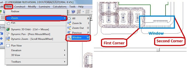
- From the menu, select VIEW, ZOOM, WINDOW. The mouse pointer will turn into an arrow, signifying that you can specify the Zoom Window.
- Left-Click the mouse at a point close to the first point indicated in the image above. The screen will now show one corner of the selection rectangle anchored at the first point, with the opposite diagonal corner of the implied window attached to the mouse arrow.
- Left-Click the mouse at a point close to the second point indicated in the graphic below.
- After the second click, the screen should look like the image shown below.
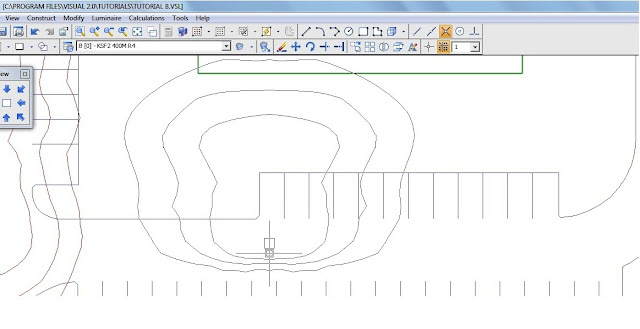
- Place three Type B luminaires as shown in the graphic below. For reference, the leftmost Luminaire is placed at a location close to (520,156,0).
IMPORTANT!
Now that you are done placing the parking lot luminaires, make sure to turn off the Intersection Object Snap by clicking it on the toolbar or selecting it from the TOOLS, OBJECT SNAP menu as shown in below image.
D- Inserting Luminaires using “Place & Aim”
The building owner has requested that we floodlight the front façade.
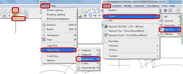
- From the VIEW MENU, select ZOOM, PREVIOUS.
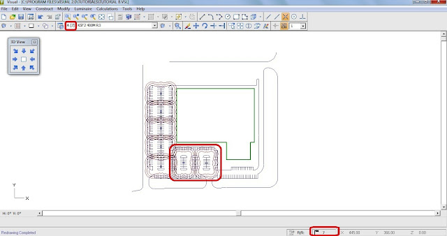
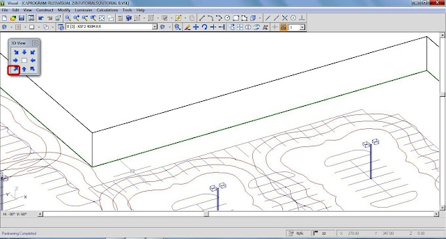
- Select the “Southwest” view using the 3-D VIEW TOOLBAR as we did before.
- From the VIEW MENU, select ZOOM, WINDOW, and select a portion of the lighting model such that the Screen looks like the graphic below.
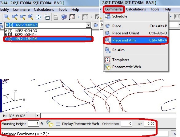
- Left Click the drop-down arrow at the right side of the Luminaire list box and select Luminaire Type C (KFL2 175M RN) from the list.
- Select PLACE & AIM from the LUMINAIRE MENU.
Note:
- The Status Bar will prompt for coordinate selection.
- The Property Bar will display edit boxes for Mounting Height, Orientation, and Tilt as before.
- An implied Luminaire symbol graphic will again be attached to the mouse crosshairs.
Used Criteria:
- The Mounting Height must be altered to (1) foot as shown in above image. The default Orientation and Tilt should be correct.
- The Type C Luminaires are to have a setback from the building of 20 feet and are to be spaced 30 feet apart. It is common to place the first luminaire half the spacing distance (15 feet, in this case) from the end of the wall. Moving the crosshairs over the bottom corner of the wall, we see that its location is approximately (247,368,0). Based on the design criteria, the first Luminaire should have location coordinates of (262,348,0).
- Press the HOME key on the keyboard to ensure that the working plane is set to X-Y at Z=0.
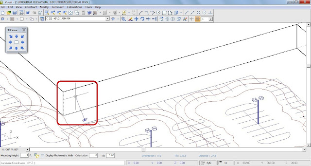
- Move the mouse crosshairs to the location (262,348,0) and Left-Click the mouse. Alternatively, you may type the coordinates into the Command Line. This will place the Luminaire.
- When the crosshairs are moved from this location, an aiming line, stretching from the luminaire to the crosshairs, will appear. As the crosshairs are moved, the luminaire will reflect the appropriate change in physical orientation and vertical tilt. In this case, a good rule of thumb is to aim the fixtures two-thirds of the way up the wall. Since the wall is 30 feet high, we want to aim the fixtures about 20 feet up the wall.
- Move the mouse crosshairs until the X-Axis of the crosshairs is coincident with the bottom of the wall.
- Press the TAB key on the keyboard to toggle the working plane to the X-Z plane. Move the mouse crosshairs vertically up the wall until the Relative Coordinate Display (in blue) reports values of (0,20,19). ;
- This indicates that the Luminaire is aimed 0 feet left-right of its center, 20 feet in front of its center, and 19 ft above its center (remember that it has a mounting height of one foot). The screen should look like the graphic below.
- Left Click at this location to set the aim point and complete the aiming of the luminaire. It is a good idea to hit the HOME key at this time to set the crosshairs back to the X-Y plane at Z=0.
- Right Click in the Design Window to terminate the Place & Aim command.
We will now array the Luminaire we just placed in order to light the entire wall.
- Press the HOME key to again to ensure that the working plane is set to X-Y at Z=0.
- From the Modify MENU, select ARRAY, RECTANGULAR.
Notes:
- The Status Bar will prompt for object selection.
- The Property Bar will present edit fields for X, Y, and Z axis quantities.

- Select the Array by Spacing option on the Property Bar. The X, Y and Z fields will now prompt for spacings.
- We would like to space the Luminaires 30 feet apart, so change the X Spacing to 30. The Y Spacing should be set to 0 because we only need one row of Luminaires.

- Left-Click the mouse on the center of the floodlight to add it to the selection set.
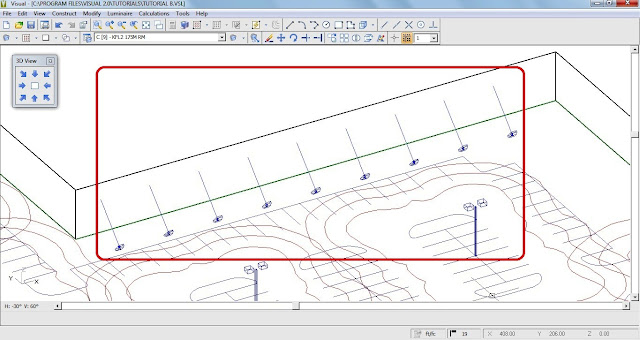
- Right-Click the mouse to indicate that you are finished selecting objects. The Status Bar will then prompt for a base point. Select the center of the existing Luminaire (262,348,0).
- Move the crosshairs along the wall to the right, and the implied array will be filled in as shown in image below. When the array fills the wall, Left Click to complete the array.
In the next Article, I will explain Step#9: how to insert Calculation Planes and printing the Final Report. Please, keep following.

No comments:
Post a Comment