
In the previous article " Area lighting Design Calculations - Part One", I indicated that the most commonly used design methods for floodlighting calculations are:
- The point-by-point method,
- The beam-lumen method, which include: IES method & CIE method.
- Isolux Diagram Method,
- Computer Aided Design.
And I explained the point-by-point method and the beam-lumen method as per IES in this previous article.
I also explained the beam-lumen method as per CIE and the Isolux Diagram Method in the previous article " Area lighting Design Calculations - Part Two ".
Today, I will explain Fourth method: Computer Aided Design for Area (flood) lighting design as follows.
You can review the following Previous Articles for more information:
Fourth: Computer Aided Design
The above methods use curves and diagrams that help in finding out the illuminance, uniformity, etc., but have disadvantages as follows:
- It takes quite a substantial amount of time,
- When a number of alternate designs have to be made, it becomes still more time consuming.
I will explain (3) software programs for outdoor lighting design which are:
- Visual Professional Edition 2.6,
- CalcuLux Area,
- DiaLux Red Version.
1- Visual Professional Edition 2.6
First: Introduction

The Visual Professional Edition is a comprehensive lighting analysis tool designed for demanding interior and exterior applications. The following list illustrates some of the features of the Visual Professional Edition:
a- True 3D Environment
Change viewpoints, zoom in/out and pan the design at anytime, even in the middle of another command. Work dynamically in any coordinate plane (X-Y, X-Z, or Y-Z) to easily create complicated architectures or to aim luminaires at specific locations. Quickly switch the active working plane at anytime.
b- Non-Orthogonal Surfaces
Create and analyze virtually any architectural space, including sloped ceilings, curved walls, domes, arches, etc.
c- Luminaire Schedule
Create and analyze virtually any architectural space, including sloped ceilings, curved walls, domes, arches, etc. Modify luminaire symbols and create custom, multi-head luminiare configurations in the symbol editor. View and download product information and specification sheets over the Internet for supported photometry files. Save and reuse schedules for quick access to favorite luminaires.
d- Flexible Calculation Grids
Create calculation grids of any shape and orientation, or place a grid on any surface with one click. Choose any normal orientation for calculation points, or create Max Spill or TV Illuminance calculation zone.
e- Professional Output
Create custom pages using the Print Editor. Print to any Windows-compatible printer or plotter.
f- CAD Compatibility
Import ACAD 2010 and earlier DWG/DXF files. Export AutoCAD 2008, AutoCAD 2000 and R14 compatible files.
Second: Installation, Downloading Database and Registration
1- Installation Steps
A. Download the setup program from https://www.visual-3d.com/software/downloadvisual.aspx. Make sure to save the setup program to your hard drive. Run the setup by double-clicking the setup file.
B. The Visual Installation program will begin running. Follow the instructions that appear on your screen.
2- Downloading Database
Acuity Lighting Group regularly updates photometric databases as products are introduced and/or changed. To download the latest photometric files visit: https://www.visual-3d.com/software/downloadvisual.aspx
Note: the Downloadable program is a 30-day trial version (including the free Basic Edition).
3- Registration

To register as a Visual user, please create an account on the Visual website: https://www.visual-3d.com/
Then obtain a license for the Professional Edition by buying a Single User License for a total price $100.00 USD.
Third: Updates and Technical Support
Third: Updates and Technical Support
1- Updates
Visit https://www.visual-3d.com/ to check for program news and updates.
Forth: Understanding the Visual Program Interface
The Visual interface consists of five fundamental elements as follows:
- The Design Environment,
- the Options Form,
- the Properties Form,
- the Luminaire Schedule Editor,
- the Print Editor.
1.1 The Design Environment

The Design Environment is the central element of the Visual interface and is where most user interaction takes place. It also serves as the gateway to all of the other elements.
This is where lighting models are constructed and analyzed to develop a final design. Each region of the Design Environment has an explicit function that remains consistent throughout program operation. The purpose of each is outlined below.
1.1.1 The Menu

As with most Windows applications, the menu is the primary means of initiating commands. All Visual commands and parameters can be accessed through the main menu. Upon selecting a menu item, a drop-down menu will appear allowing further selection of the desired command or parameter.
The presence of a right-arrow indicates that further command specification is required in the form of a sub-menu. The sub-menu will automatically appear when the mouse cursor is moved over any menu item containing a right-arrow. Later, we will come back to the Menu Commands.
1.1.2 The Toolbars
Alternative means of accessing frequently used commands and parameters. The toolbars consist of command buttons and drop-down list boxes that are arranged for ease of identification.
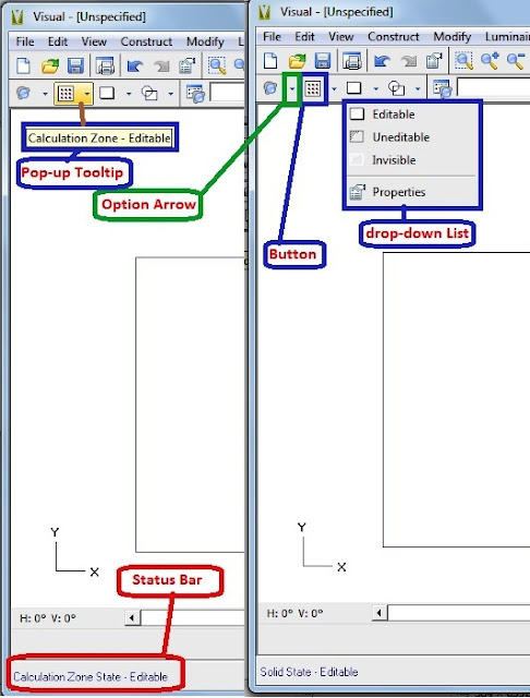
All object construction commands reside on a single toolbar, for instance. In the toolbar above, a leader points to a small options arrow. To select the command as indicated, select the existing button. To view the available options, click on the option arrow and select from among the subsequent list.
To ascertain the function of a button, hold the mouse pointer steadily over the button. The command will be immediately identified on the status bar and a pop-up tooltip will appear next to the mouse pointer.
1.1.3 The Design Window
The Design Window comprises the majority of the Design Environment screen. This is where lighting models are constructed, displayed and analyzed.
In the lower-left corner of the Design Window is a Coordinate Axes Icon that indicates the orientation and/or direction of the coordinate axes at all times.
Think of the Design Window as your view port to the lighting model. There are a number of ways to manipulate the view port. It can be translated (left, right, up, or down), moved rotationally around the lighting model, and zoomed in and out. Later, I will explain how to choose a suitable view.
1.1.4 The Status Bar

The Status Bar is located at the bottom of the Design Environment screen. The Status Bar provides information related to the current command, the cursor position within the design space, and the total number of active Luminaires present in the model.
Always present, it consists of the following elements:
- Command Line,
- Absolute and Relative Coordinate Displays,
- Calculation Status Icon,
- Units Indicator,
- Interior/Exterior Icon
- Active Luminaire Counter.
A- Command Line
The purpose of the Command Line is to provide dynamic textual feedback and allow coordinate entry related to commands during program operation. Once a command has been initiated, the Command Line prompts the user for subsequent information such as coordinate and object selection.
In certain cases, numerical coordinate entry is supported and the Command Line will convert to a text entry box to allow such data to be entered manually. Later, I will explain how to enter the coordinates.
B- Absolute Coordinates
Absolute Coordinates report the exact location (Cartesian X,Y,Z) of the mouse crosshairs withinthe model space at all times.
C- Relative Coordinates
Relative Coordinates report the location (Cartesian X,Y,Z) of the crosshairs within the model space relative to a previously selected coordinate. Relative Coordinates are only reported for subsequent coordinate selections and are useful when relative distances are more convenient or intuitive than absolute locations. Relative Coordinates may also be displayed in polar form.
D- Calculation Status Icon
The Calculation Status Icon indicates whether the lighting model has been calculated. If the model has been calculated and the illuminance values are valid the Icon will appear as an illuminated lamp over a calculator. If the model has not been calculated the lamp is gray.
E- Units Indicator
The Units Indicator displays the current units settings for the lighting model. The input units of distance (feet or meters) are displayed first, followed by the output units of illuminance (footcandles or Lux).
F- Interior/Exterior Icon
The Interior/Exterior Icon indicates whether the current lighting model is an interior model or an exterior model. If the model is an interior lighting model then a small interior fixture icon is displayed. If the model is an exterior lighting model then a pole mounted fixture icon is displayed.
G- Luminaire Counter
As the name implies, the Luminaire Counter provides an up-to-date count of the number of active Luminaires present the lighting model.
1.1.5 The Property Bar
The Property Bar is a dynamic feature that allows unique attributes such as text description, reflectance, and height to be assigned to objects as they are being created. It too, is located along the bottom of the Design Environment screen just above the Status Bar.
The Property Bar is considered dynamic because its contents change depending on the active command.
1.2 The Options Form

The Options Form is accessed through the TOOLS MENU of the main menu. This is where parameters affecting the global operation of Visual reside.
The Options Form Tabs provides a means for customizing the interface to meet specific needs and/or user preferences. Each tab includes options which are logically grouped and labeled for easy identification. Graphics are included where appropriate. Later, I will explain the Option Form in detail.
1.3 The Properties Form

The Properties Form is accessed through the EDIT MENU of the main menu. This is where the attributes of Visual objects such as Calculation Zones, Luminaires, and Solids are edited after their initial creation.
The Properties Form Tabs provides a means of either modifying object attributes singularly or in groups. This permits rapid model modification and "what if" type analyses to be performed with little effort.
Like the Options Form, The Properties Form Tabs include options which are logically grouped and labeled for easy identification. Later, I will explain, in detail, the use of the Properties Form.
1.4 The Luminaire Schedule Editor

The Luminaire Schedule Editor is accessed through the LUMINAIRE MENU of the main menu. This is where the Luminaire Schedule is developed to establish the various Luminaire Configurations available for use within the Design Environment. Luminaire Types are arranged in a scrolling spreadsheet format for easy and intuitive assignment of photometric information, symbols, descriptions, and design templates.
Photometric and descriptive information is accessed by selection of a valid photometric file. Later, I will explain, in detail, the Luminaire Schedule Editor.
1.5 The Print Editor

The Print Editor is accessed through the FILE MENU of the main menu. This is where graphics and other information are composed to produce the printable results of a Visual lighting model.
The Print Editor provides a means of developing customized multi-page, multi-view documents.
Like the Design Environment, the Print Editor is equipped with menus, toolbars, and a Status Bar. Items are placed on the page and appear as they will in the printed output. Various views of the lighting model may be included at any scale along with title blocks, statistics, luminaire schedules, luminaire locations, and custom notes. Additionally, text annotations and standard graphic images may be added to provide an additional dimension of customization. Later, I will explain, in detail, the Print Editor.
In the next Article, I will explain the menu functions and other forms for Visual Lighting software. Please, keep following.

No comments:
Post a Comment