In this topic and in the next topics, I will give a little more detailed description of transformer’s main parts; core, winding, tank, Insulation materials and cooling materials.
Cores:
1- Core Material:
Transformer cores are built from many layers of thin sheets of steel and silicon alloy, the use of silicon (3% or below) increase the specific electrical resistance which reduces the eddy current losses in the core.
The core sheets must be insulated from each other to minimize the eddy currents with an appropriate insulation material.
Eddy currents losses in the core steel are preoperational to the square of the thickness, therefore the steel sheets have to be thin to reduce the no-load losses and typical thickness is from 0.18mm to 0.30 mm.
fig.1
2- Core Construction: see fig.1
Limbs: vertical steel sheets magnetically connected with each other at the upper and lower ends by Yokes.
Yokes: Horizontal steel sheets magnetically connected with each other at the right and left ends by Limbs.
Windows: spaces available between the Limbs and Yokes.
3-Core configurations:
Case one: 3 phase transformers - three Limbs core see fig.1
Nos. of windings = Nos. of Limbs (each one Transformer winding is located on one Limb)
The sum of windings voltages at any instant = Zero
The sum of windings currents at any instant = Zero
The sum of Limbs Fluxes at any instant = Zero
Flux generated on each Limb will be divided in the Yokes and return in the other two Limbs. See fig.1
For the same amount of flux passing through Limbs and Yokes, The yokes cross sectional area = the Limbs cross section area
fig.2
Case 2: 3 phase transformers - Five Limbs core see fig.2
Nos. of windings < Nos. of Limbs (three windings located on three Limbs and additional two outer side Limbs)
Flux generated on each Limb will be divided into two half in each Yoke. So, the yokes and side Limbs will carry half of the flux, therefore the yokes cross sectional area = the side Limbs cross section area = ½ the main Limbs cross section area
This will give ability to reduce the transformer dimensions to be suitable for the transportation purposes
fig.3
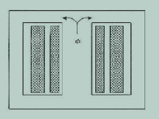
Case 3: single phase transformer – one Mid Limb with windings and two side Limbs for flux return see fig.3
Case four: single phase transformer – two Limbs with windings see fig.4
This design of case there is more economical than that of case four , but the case four design will be more suitable in case of using two separately derived systems.
in the Next Topic, I will Continue explaining the Transformer Design - Windings.


Best of luck in your work.
ReplyDelete