How to Read and Interpret Electrical Shop Drawings –Part Four


Today, we will explain the following:

  • Basic Elements of Electrical Drawings,
  • Types of Electrical Drawings,
  • Single-Line /One-Line Diagram - Part one.


8- Basic Elements of Electrical Drawings


An electrical drawing is a type of technical drawing that shows information about power, lighting, and communication for an engineering or architectural project.


Any engineering drawing consists of (6) basic elements  (see above figure) as follows:
 
  1. Field of the drawing.
 
Field of the drawing: it is the main body or main area of the drawing, excluding the title block, rev block, and other drawing elements.
 
For reviewing each drawing element in above please click its name to open the link or review our course ED-1: Electrical Drawings Course” for more information.


9- Types of Electrical Drawings


The electrical drawings can be categorized to many types according to the following:
 
  1. According To The Stage Of Project,
  2. According To The Drawing Purpose.
 
Note:
 
All types of electrical drawings are two dimensional drawings, the three dimensional drawings (like the isometric drawings) are not common for using as electrical drawings.


First: According To the Stage of Project
 
There are many types of drawings that you will deal with during any project life as follows:
 
  1. Shop drawings: Part One - Part Two
  2. As built drawings
  3. Composite (Coordination) drawings
 
 
For reviewing each Electrical drawing type as per the stage of project in above please click its name to open the link or review our course ED-1: Electrical Drawings Course” for more information.


Also, in course ED-1: Electrical Drawings Course”, You can review the following articles about the electrical shop drawings:
 
  • Shop Drawings Definition
  • Shop Drawings importance
  • Shop Drawing Stamps
  • Important Notes for Shop Drawings approval
  • Shop drawings submittals classifications
  • Contractor's responsibility in shop drawing development
  • Consultant/Engineer’s responsibility in shop drawings approval
  • Improper Use of Shop Drawings
  • Did the shop drawings affect the construction cost?
  • Comparison between shop drawings and construction drawings


Second: According To the Drawing Purpose
 
There are many types of electrical drawings which range from the very simple to the very complex. Each of these electrical drawings has a specific purpose and distinguishing features that set it apart from the others.
 
You should be able to recognize the relationship between these various types, their distinguishing features, and the purpose of each type of drawings.
 
 
Electrical drawings as per their purposes usually divide to main types as follows:
 
  1. Electrical Diagrams,
  2. Electrical Layouts (plans),
  3. Electrical Schedules.


1-  Electrical Diagrams
Diagrams show the electrical path, device wiring, and sequence of operation, device relationship, or connections and hookups of the electrical installation.


Electrical diagrams include the following sub-types:
 
  1. One-Line Diagram,
  2. Three-Line Diagram,
  3. Schematic Diagram, Or Elementary Diagrams,
  4. Connection/Wiring Diagram,
  5. Interconnection Diagram,
  6. Block Diagram,
  7. Logic Diagram,
  8. Ladder Diagrams,
  9. Riser Diagrams,
  10. Pictorial Diagrams,
  11. Terminal Diagram,
  12. Combination Diagrams,
  13. Electrical Arrangement Drawings,
 
Electrical symbol is a small picture or image called a pictogram used to represent


2- Electrical Layouts (plans)
 
The electrical layout/plan determine where each electrical device and piece of equipment is to be located related to the architectural features of the area. It shows where and how the conductors/conduits are to run. It helps locate the incoming service. Electrical plans are also used for estimating installation and material costs. By examining a plan, you can take off, that is, count, the number of switches, outlets, fixtures, feet of wire, etc., that may be required for a particular job.


Electrical layouts include:
 
  1. Lighting and power Plan Drawings,
  2. Cable and Raceway (Conduit) Drawings,
  3. Ground Grid Plan,
  4. Equipment Layout Drawings,
  5. Low voltage systems Plan Drawings,
  6. Utility (Site) Plan,
  7. Underground Utility/Manhole Drawings,
  8. Overhead Pole Line Layout Drawings,
  9. Switchgear Layout Drawings,
  10. Motor Control Center (MCC) Layout Drawings,
  11. Installation Detail Drawings.


3- Electrical Schedules
 
  • An electrical schedule is a table that contains a list of electrical equipment and technical notes.
  • The purpose of a schedule, in general, is to provide a simple means (graphical or tabular charts) of representing or recording necessary electrical data for various purposes (e.g., construction, operations, maintenance).
  • Electrical schedules are not only powerful time saving tools for draftsmen and engineers, but they also save valuable time for technical specification writers and job site workers.
 
  • There is no standard for drawing any particular schedule. Many organizations standardize their schedules, where practical. However, there are many types of electrical schedules as follows:
 
  1. Cable and Raceway Schedules,
  2. Panelboard Schedules,
  3. Circuit Breaker Switchgear Schedule,
  4. Motor Control Center (MCC) Schedule,
  5. Equipment Schedules,
  6. Lighting Fixture and Receptacle Schedules.


1- Electrical Diagrams


1- Single-Line /One-Line Diagram


A- Characteristics of Single-Line Diagram
 
  • A single-line or one-line diagram is the most commonly used diagram in an industrial power system.
  • This diagram uses single lines, standard graphical symbols, and standard nomenclature to show the power paths of an electrical circuit or a system of circuits.
  • A single-line diagram can be used to show essential components and their function in simplified form.
  • In a single-line diagram, the multiple conductors of power circuits and control circuits are shown as single lines.
 
The below Figure shows an example of a single-line diagram.


Note:
  • For maximum usefulness, the relative physical arrangement and orientation of the electrical system should be shown on the one-line diagram.
  • We will use the above single-line diagram throughout these articles for explaining how to interpret this type of electrical diagrams. You can download a PDF copy of this single-line diagram by following the link.


B- Purposes of Single-Line Diagram
 
 
A single-line diagram has multiple uses in the following cases:
 
  1. Power System Studies,
  2. Operations and Maintenance,
  3. Construction.
 
 
1- Power System Studies
 
  • The one-line diagram is most commonly used in the performance of power systems studies. So, the following information should be provided, as a minimum, on the one-line diagram, regardless of the type of power system study being performed:
 
  1. Bus current and voltage ratings,
  2. Short-circuit current available (optional),
  3. Voltage and current ratios of instrument transformers,
  4. Protective device (circuit breakers, fuses) ratings,
  5. Functions of relays indicated by device numbers,
  6. Ratings, type, and impedance of motors and transformers,
  7. Connections (i.e. delta or wye) of transformers,
  8. Number, length, size, and type of conductors and conduit.
 
  • The final application of the drawing (short-circuit study, coordination study, construction, etc.) will determine the exact information on the one-line diagram. For example, impedance of a motor is required for a short-circuit study but not for a coordination study. Relay and adjustable settings of circuit breakers are required for a coordination study but are not required for a short-circuit study.
 
 
2- Operations and Maintenance
 
  • The one-line diagram is also commonly used by technicians to operate and maintain the plant electrical distribution system. For example, the one-line diagram is used to determine which breakers or switches should be closed or opened to switch to alternate sources of power due to a fault on the system.
  • Another example is that the one-line diagram is used to perform “locking and tagging” procedures when equipment is to be removed from service.
  • Both of these uses of the one-line diagram point out that the diagram must be kept up-to-date and accurate. Use of inaccurate data (one-line diagram) for a power systems study could result in additional costs; use of inaccurate data for switching purposes or locking and tagging procedures could result in loss of life.
 
3- Construction
 
  • Probably the least common use of the one-line diagram is for construction purposes.
  • Electricians usually will require more details to construct or install electrical equipment than is available on the one-line diagram. Some of these “more detailed” drawings will be described in the paragraph of Information elements required for interpreting one-line diagrams.


C- Arrangement of Components on Single-line Diagrams

  • On one-line power diagrams, components are usually arranged in order of decreasing voltage levels.  The highest voltage component is shown at the top right of the drawing. 
  • In order to find out how power is supplied to a component, start at the component and trace the flow of power backwards through the drawing.  This method will be most useful in locating the correct circuit breaker to isolate a component for maintenance.


D- Interpreting Single-Line Diagrams
 
The interpretation of single-line diagrams is explained in this section under the following major subject headings:
 
  1. Informational Elements,
  2. Details Variations,
  3. Relationships between one-line diagrams and associated reference documents.


D.1- Informational Elements
 
The following informational elements of a single-line diagram are explained in this section:
 
  1. Point of connection to the utility company,
  2. Identification of buses, substations, generators, motors and other equipment,
  3. Ring Main Units data,
  4. Automatic voltage regulator data,
  5. Power transformer data,
  6. Switchgear data,
  7. Protective device ratings,
  8. Instrument transformer data,
  9. Metering, relaying, and control device data,
  10. Available short circuit current data,
  11. Switch or breaker status,
  12. Key interlock systems,
  13. Protective relay trip logic,
  14. Generator data,
  15. Load bank data,
  16. Connected load data,
  17. Cable ratings,
  18. Bus ratings,
  19. Future installation.
 we will explain all the above points in the next paragraphs and next Articles.


D.1.1 Point of Connection to the Utility Company
 
  • The point in the power distribution system where it is connected to the utility company is shown on a one-line diagram as a short horizontal line. This horizontal line is accompanied by information concerning the nominal rated voltage and the values of fault megavolt-amperes (MVA) of the utility company’s circuit. Because this point in the power distribution system is the usual location for the utility company’s revenue meters, the point of connection is sometimes called the metering point.
 
  • As an example, the one-line diagram Fig. shows the point of connection to the utility at the top of the diagram. The printed information indicates that the power circuit’s nominal voltage rating is 13.8 kV, its frequency rating is 60 Hz, and that it is a three phase circuit.
 
Information needed from the Utility Company:
 
  1. The three-phase fault MVA (MVAs.c),
  2. The three-phase X/R ratio,
  3. The fault clearing time in sec.


D.1.2 Identification of buses, substations, generators, motors
 and other equipment
 
  • Buses, substations, generators motors and other equipment are identified with alpha-numeric designations that match the designations on other diagrams, drawings, lists, and equipment identification plates.
  • The single line diagram in Fig. have equipment designations such as CB1, CB2, CB3, CBA, 4-POLE ‘PSGE’, and 4-POLE ‘PSGU’.


D.1.3 Ring Main Units data

Function:

The RMU is a compact unit combining all MV functional units to enable connection, supply and protection of one or two transformers on an open ring or radial network by one of the following methods:
 
  1. By a fuse-switch combination,
  2. By a circuit breaker with self-powered protection unit,

Overview of RMUs


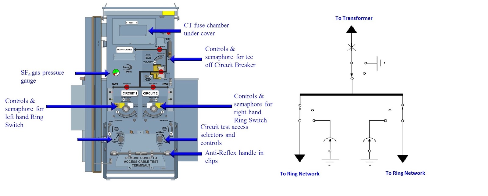
1- In an electrical power distribution system, a ring main unit (RMU) is a factory assembled, metal enclosed set of switchgear used at the load connection points of a ring-type distribution network.
This type of switchgear is used for medium-voltage power distribution, from 7200 volts to about 36000 volts.

2- Ring main units can be characterized by their type of insulation, air, oil or gas.
It includes in one unit two load break switches that can connect the load to either or both main conductors, and it includes a fusible switch or circuit breaker that feed a distribution transformer. The metal enclosed unit connects to the transformer either through a bus throat of standardized dimensions, or else through cables and is usually installed outdoors. Ring main cables enter and leave the cabinet from bottom.

3- The switch used to isolate the transformer can be a fusible switch, or may be a circuit breaker using vacuum or gas-insulated interrupters. In case a circuit breaker is the switching device, it is also equipped with protective relaying, either with a very basic self-powered type or a more advanced one with communication capabilities.
 
4- All of the switching devices are of three-position design, having the possibility to close or open or earth the feeder in question.
 
There are many combinations of RMUs as shown in below figure:


The impotent data need for specifying the RMUs are:
 
  • Nominal system voltage,
  • Corresponding highest system voltage,
  • Frequency,
  • Number of phases,
  • Neutral earthing type,
  • Fault level (minimum),
  • Max. Ambient air temperature.


In the next article, we will continue explaining the Interpreting Single-Line Diagrams. So, please keep following.
 

The previous and related articles are listed in the below table:

 
Subject of Previous Article
Article
1- Overview for the articles/courses that give a preliminary explanation for the different Types of Electrical drawings.
2- Electrical Drawings Glossary.


3- Resources used to Read and Interpret Electrical Drawings.
 
 
4- Electrical Symbols and Abbreviations
5- Electrical Abbreviations
6- Device Function Numbers
7- Drafting Practices Using Graphical Symbols and abbreviations


Back To 
 
Electrical Shop Drawings Course


2 comments: