Voltage Drop Calculations- Part Six


In article  " Voltage drop calculations- Part One ", I indicated that there are eight methods for Voltage Drop Calculations as follows: 


1- Ohm’s Law Method, 


2- European method, 
3- U.S method which divided to: 

  • Circular-mils method, 
  • Chapter (9) tables method. 
4- Approximate Mathematical method, 
5- Quick On-Line method, 
6- Ampere-Feet method, 
7- Lookup tables, 
8- Excel spreadsheets. 
And I explained the first two methods: Ohm’s Law Method and European Methods in this Article. 

And, I explained the third method: U.S Method- Circular-mils Method In Article 
Voltage drop calculations- Part Two  ", 


And, I explained the third method: U.S Method- Chapter (9) tables Method In Articles: 


And, in Article 
Voltage Drop Calculations- Part Four ", I explained the following methods for Voltage Drop Calculations:
  • Approximate Mathematical method,
  • Ampere-Feet method, 
  • Lookup tables, 


Also, in Article " Voltage Drop Calculations- Part Five ", I explained the Quick On-Line Method with (8) Voltage Drop Calculators.


Today I will continue explaining other methods for Voltage Drop Calculations as follows. 


8- Excel Spreadsheets Method for Voltage Drop Calculations


8- Excel Spreadsheets Method for Voltage Drop Calculations

Under this method, I will explain the following excel spreadsheets for Voltage Drop Calculations:

First: Excel Spreadsheet for US / NEC Methods:
  1. Excel Spreadsheet for Voltage Drop Calculator,
  2. Excel Spreadsheet for Voltage Drop Calculations,
  3. Siemens Voltage Drop Calculations Spreadsheet.


Second: Excel Spreadsheet for European Method /Code
  1. Excel Spreadsheet for Cable Sizing, Voltage Drop Calculation and Circuit Breaker Selection,
  2. Excel Spreadsheet for 3-Phase Voltage Drop Calculations.


First: Excel Spreadsheet for US / NEC Methods:


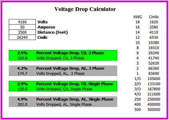
1- Excel Spreadsheet for Voltage Drop Calculator

This Excel Spreadsheet Calculate the Voltage Drop as per US- Circular Mils Method.


How to use this Excel Spreadsheet:

1- Put the input data which are:

  • Voltage in Volts,
  • Load Current in Amps,
  • Distance in Feets,
  • Cable Cross section Area in Cmils.


Note: if you have the Cable Cross section Area in AWG/Kcmil use the shown table to get the equivalent Cmils.

2- Get Voltage drop (V D) in V from the following Formula:

  • Voltage drop (V D) 3 Phase = 1.73 X I X L X K / Cmils
  • Voltage drop (V D) Single Phase = 2 X I X L X K / Cmils
  • Where K=12.6 for CU and K=21.2 for AL


3- Get Voltage drop (V D) in percent from the following Formula:

 (V D) % = Voltage drop (V D) in V x 100 / Voltage

4- From the Results section, select the Result that match with the actual method of installation from the following choices:

  • Copper and 3 phase,
  • Aluminum and 3 phase,
  • Copper and single phase,
  • Aluminum and single phase.


5- If the (V D %) > the predetermined Value according to Country Regulations (2.5 % or 3%), change the Cable Cross section Area in Cmils with a higher size.


2- Excel Spreadsheet for Voltage Drop Calculations

This Excel Spreadsheet Calculate the following as per US- Chapter (9) Tables Method:
  • Voltage Drop,
  • Minimum Wire Size for Voltage Drop,
  • Maximum Distance with the Load.


How to use this Excel Spreadsheet:


1- Fill in blank cells 1 to 8 as follows:

  • Cell# 1: Select Voltage from the drop down menu which include values of (120, 208, 240, 277 or 480 V).
  • Cell# 2: Select the Maximum desired Voltage Drop Percent from the drop down menu which include values of (1% to 5%).
  • Cell# 3: Select Phase Type from the drop down menu which include values of (single phase and three phase).
  • Cell# 4: Select the type of wire from the drop down menu which include values of (Stranded Copper Uncoated, Stranded Copper Coated and Stranded Aluminum).
  • Cell# 5: Select the size of wire (if known) from the drop down menu which include values of (18 AWG to 2000 Kcmil).
  • Cell# 6: Enter the length of wire (0 – 5000 feets) (if known).
  • Cell# 7: Enter Amps (0 – 6000 A) (if known).
  • Note: If you leave only one entry blank in cells 5, 6 or 7, then a recommended maximum value will appear to the left of the blank cell.
  • Cell# 8: Enter the number of Parallel wires (1 is non-parallel, 2-25 parallel pairs).


Note: if the wire is smaller than 1/0 AWG, then Parallel wires are not allowed except per 310.4 exceptions.

2- The Result Window will show the following Calculated information (in grey color) which are:
  • Cell# 9: Maximum Voltage Drop Allowed
  • Cell# 10: Minimum Voltage Allowed At Load
  • Cell# 11: Multiplier
  • Cell# 12: Resistance/1000 Feet of Wire
  • Cell# 13: Wire Size
  • Cell# 14: Distance
  • Cell# 15: Maximum Amps
  • Cell# 16: Minimum Number of Parallel Wires
  • Cell# 17: Actual Voltage Drop
  • Cell# 18: Actual Voltage Drop with Load
  • Cell# 19: Voltage Difference
  • Cell# 20: Total Resistance per Foot
  • Cell# 21: Minimum Wire Size for Voltage Drop
  • Cell# 22: Maximum Distance with This Load
  • Cell# 23: Maximum Ampacity of the Wire in Cell 13 per Table 310.16 of the 2002 NEC
  • Cell# 24: Ampacity Above or Below Load


Notes:

  • All the correct calculated data in the result window will appear in green color and the wrong data will appear in red color and need to recalculate with a higher wire size.
  • The formulas used for getting the calculated information in the result window are shown in below image.


  • The ampicity of the wire in cell 13 is given in cell 23, if this cell turns red, the wire size in cell 13 is not large enough to carry even the minimum load.
  • This method doesn’t consider any other factors like insulation type, continuous load, correction factors or adjustment factors.
  • Voltage drop calculations and table 310.16 are not the only considerations when sizing conductors. Many other factors must be considered such as:

  1. The type of the load
  2. The ambient temperature
  3. The type of insulation
  4. The association with other conductors
  5. The temperature rating of the equipment
  6. The type of environment
  7. The size of the breaker
  8. The type of the circuit (branch, feeder, service, grounding, or control)
  9. Continuous load
  10. Others


3- Siemens Voltage Drop Calculations Spreadsheet 

This voltage drop calculator will provide an approximate value for use in project design. You can review this spreadsheet in the Previous Article "Siemens Voltage Drop Calculations Spreadsheet ".


Second: Excel Spreadsheet for European Method /Code


1- Excel Spreadsheet for Cable Sizing, Voltage Drop Calculation and Circuit Breaker Selection


This Excel Spreadsheet Calculate the following as per European Method /Code:
  • Cable Sizing,
  • Voltage Drop Calculation,
  • Circuit Breaker Selection


How to use this Excel Spreadsheet:


First: for Cable Sizing


1- Put the input data (as in below image) which are:

  • No Load Voltage (Uo) in Volts,
  • Power Factor (P.F),
  • Rated Voltage (Vn) in Volts,
  • Ambient Temperature in C deg. (to be selected from the drop down menu),
  • Max. Conductor Temperature in C deg.,
  • Route length of Cable (L) in meters,
  • Load Power (PL) in watts.


Input Data


2- Get the Rated Current (IL) in Amps from the following Formula:
IL = PL / ( √3 x Vn x PF )


Steps #2 to 4


3- Select the suitable Cable Size (in mm2) from the Drop down menu with the following condition:
The Cable Ampacity (IZ) > the Rated Current calculated from step #2 above.

4- If the selected Cable Ampacity < the Rated Current calculated from step #2 above, a warning Message in red color will appear telling you that the selected cable cross section is small and you must re-select a higher size from the drop down menu.

5- Select the installation method and details from the drop down menus which are required to Derate the selected cable Size according to the actual installation conditions.


Step#5

6- Get the Air Temperature and Grouping Derating Factors based on step#4 above.


7- Get the corrected (De-Rated) Current in Amps from the following Formula:

De- rated current of Cable = Air Temp. Factor x Grouping Factor x Rated current of Cable


Steps#6 to 8


8- If the De- rated current of Cable < Rated current of Cable x Over capacity factor, a warning Message in red color will appear telling you that the selected cable cross section is small and you must re-select a higher size from the drop down menu of step#3.

9- Repeat the above steps till you didn’t get any warning messages.


Second: Voltage Drop Calculations(see below image)


1- Put/get the input data which are:

  • AC Resistance of Cable (RAC) in Ω/Km,
  • Inductance of Cable (X) in Ω/Km,
  • P.F = Cos (φ),
  • Sin (φ).


2- Get Voltage drop (V D) in V/Amp/Km from the following Formula:
  (V D) Voltage drop of cable (L) per Amp. Per length = √3 × (R (AC) 90°×Cos (φ) + X × sin (φ))


3- Get Voltage drop (V D) in Volts from the following Formula:
Voltage drop (V D) = (V D x I L x L)

4- Get Voltage drop (V D) in Percent from the following Formula:
(V D %) = (V D cable *100 / V n)

5- if the (V D %) > the predetermined Value according to Country Regulations (2.5 % or 3%),a Warning message in red color will appear telling you that the Voltage Drop % is High and you must re-select a higher size from the drop down menu of step#3 in cable Sizing Section.

Third: Circuit Breaker Selection

1- Select the Circuit Breaker Rating in Amps from the drop down menu to verify the following formula:
Rated Current (IL) ≤ CB Rating ≤ the Cable Ampacity (IZ)


2- Excel Spreadsheet for 3-Phase Voltage Drop Calculations

This Excel Spreadsheet Calculate only the 3-Phase Voltage Drop as per European method /Code.


How to use this Excel Spreadsheet:

1- Put the required general data which are:

  • Date: put the date of calculations, you may need to know the date of making these calculations
  • Project name: put the name of the project
  • Building name: put the name of the building, if there are more than one building
  • Cable Feed: put the name of the panel or the load that you want to calculate the voltage drop for it


2- Put the Load data which are:

  • Load power (KW): put the load or panel power in KW
  • Voltage (V): put the line to line voltage in Volts
  • Load Current (A): Calculated Value of Load Current in Amps from the following Formula:


Load Current (A) = (Load power (KW) x 1000) / (√3  x Voltage (V) x P.F)

Note: If P.F is unknown, you can use P.F = 0.85


3- Put the Cable Data which are:

  • Cross Section Area (A) in mm2
  • Length (L) in Meters
  • K   (mV/m/A)


4- Get Voltage drop (V D) in Volts from the following Formula:

Voltage drop (V D) = K x Load Current (A) x Length (L) / 1000


5- Get Voltage drop (V D) in Percent from the following Formula:

(V D %) = (V D x 100 / Voltage)


6- if the (V D %) > the predetermined Value according to Country Regulations (2.5 % or 3%), you must re-select another cable with higher size and repeat the calculations.


Notes:
  • these calculations are for 3 phase only,
  • for branch circuit, if the voltage drop % exceeds 3% chose another cable with the next higher C.S.A,
  • for branch circuit + feeder, if the voltage drop % exceeds 5% chose another cable with the next higher C.S.A.


In the next Article, I will Explain More Examples for Cable Sizing, Overcurrent Protection and Voltage Drop Calculations. Please keep following.


End of Course EE-4


1 comment: