
In the previous article “ Calculux Software for Lighting Design – Part Five “, I explained How to add furniture, Task and Accent Lighting to a place.
Today I will explain how to add additional items like Curtain, windows and doors to a project as follows.
You can review the following previous articles for more information and good following:
How to add Indirect lighting, Curtain, Painting, Whiteboard, Desk, Conference table, Accent lighting, Door, Window and false ceiling?
Example#3:
Design a general lighting scheme of a director room using CALCULUX. The office details are as follows:
- Room dimensions: Width 4.70 m- Length 7.50 m - Height 2.70 m (= height of the system ceiling)
- Room reflectances: Windows (on the left) 0.10 - Other walls 0.30 - Ceiling 0.70 - Floor 0.10
- Following luminaire types will be used:
- Task TPH601/128 C7-60 and TBS630/314 C7-60
- Conference TPH601/128 MD and MASTERLINE PLUS 35W 10D
- Curtain and Cupboard FBS145/118
- Painting MASTERLINE PLUS 50W 24D
- Whiteboard MASTERLINE PLUS 50W 38D
- Indirect QFG101/300
The luminaires will be mounted in or on a system ceiling (0.6 m x 0.6 m modules).
Answer:
Step#1: Starting a new Project
- Select New Project from the File menu.
- A new empty window will be created. You can maximize the view if you wish.
Step#2: Entering Project Information and Project Options
- Select Project Info from the Data menu.
- enter the following data in below table :
In the
Project Tab
|
Name:
|
Director Room
|
Subname:
|
Example 3
|
|
Remarks:
|
Design for
desk, conference and presentation
lighting using
light regulation factors
(LRF).
|
|
Designer:
|
put 'Your Name'
|
|
In the
Customer tab:
|
put data
about your customer,
|
|
In the
Company tab:
|
you can enter
company information or select a vignette file by clicking Browse.
|
|
- Click OK.
- Select Project Options from the Data menu.
- Select the General tab.
- In the Calculations box, enter: Project Maintenance Factor 0.80
- Click OK.
Step#3: Specifying the Room

- Select Room from Data Menu.
- Select the Definition tab.
a- In the Dimensions box, enter the dimensions of the room:
- Room Width 4.70 m
- Room Length 7.50 m
- Room Height 2.70 m
- Working Plane Height 0.80 m
- In the Position box, enter the position of the Front Bottom Left corner of the room:
- Front Bottom Left X = 0.00 m, Y = -3.75 m (i.e. The Y= 0 axis is the middle of the room).
Note: Due to the windows and curtain the value of the reflectance of the left wall has to be changed. Enter: Left 0.10
- Click OK.
Step#4: By means of the Drawing function, two windows, a door, a painting, a whiteboard, a desk, a computer desk, a cupboard and a conference table will be added to the room.
- Select Drawings from the Data menu.
1- Adding the windows and door
- Click Add, then select Rectangle.
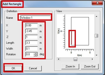
- In the Add Rectangle dialogue box, set the following parameters: Name Window 1, X 0.00 m, Y -3.45 m, Z 1.00 m, Length 3.30 m, Width 0.10 m and Rotation 0.00 deg
- Click OK.
- Click Duplicate.
- In the Add Rectangle dialogue box, set the following parameters: Name Window 2, X 0.00 m, Y 0.15 m, Z 2.10 m, Length 3.30 m, Width 0.10 m and Rotation 0.00 deg
- Click OK.
- Click Add, then select Rectangle.
- In the Add Rectangle dialogue box, set the following parameters: Name Door, X 4.60 m, Y 2.60 m, Z 2.10 m, Length 0.80 m, Width 0.10 m and Rotation 0.00 deg
- Click OK.
2- Adding a Painting and Whiteboard
- Click Add, then select Rectangle.
- In the Add Rectangle dialogue box, set the following parameters: Name Painting, X 1.10 m, Y -3.75 m, Z 1.60 m, Length 0.05 m, Width 0.80 m and Rotation 0.00 deg
- Click OK.
- Click Add, then select Rectangle.
- In the Add Rectangle dialogue box, set the following parameters: Name Whiteboard, X 1.80 m, Y 3.70 m, Z 1.20 m, Length 0.05 m, Width 1.20 m and Rotation 0.00 deg
- Click OK.
3- Adding the furniture
- Click Add, then select Rectangle.
- In the Add Rectangle dialogue box, set the following parameters: Name Bureau, X 2.30 m, Y -3.00 m, Z 0.80 m, Length 1.80 m, Width 0.80 m and Rotation 0.00 deg
- Click OK.
- Click Add, then select Rectangle.
- In the Add Rectangle dialogue box, set the following parameters: Name Computer Table, X 3.10 m, Y -2.00 m, Z 0.80 m, Length 0.80 m, Width 0.80 m and Rotation 0.00 deg.
- Click OK.
- Click Add, then select Rectangle.
- In the Add Rectangle dialogue box, set the following parameters: Name Cupboard, X 4.10 m, Y 0.60 m, Z 1.50 m, Length 1.20 m, Width 0.60 m and Rotation 0.00 deg
- Click OK.
- Click Add, then select Rectangle.
- In the Add Rectangle dialogue box, set the following parameters: Name Conference Table, X 1.00 m, Y 0.70 m, Z 0.80 m, Length 2.20 m, Width 1.00 m and Rotation 0.00 deg.
- Click OK.
After adding all the furniture the room shape will be as follows:

Step#5: Drawing the system ceiling
In this section the system ceiling (0.60 m x 0.60 m modules) will be added to the room.
Note: While this version of Calculux Indoor has no special drawing feature for system ceilings, each line of the system ceiling has to be drawn separately.
1- Drawing the lines in Y-direction (line spacing 0.60 m)
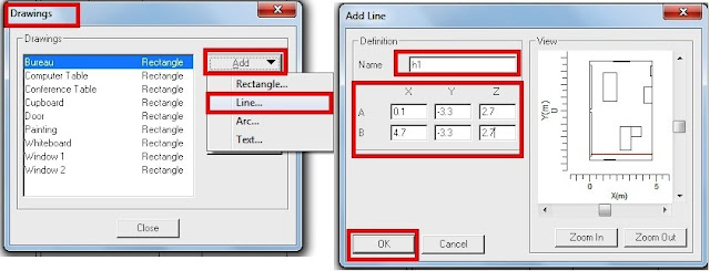
- Click Add, then select Line.
- In the Add Line dialogue box, set the following parameters:
- Name Ceiling, line h1
- Point A X = 0.10, Y = -3.30, Z = 2.70
- Point B X = 4.70, Y = -3.30, Z = 2.70
- Click OK, then Duplicate.
- In the Add Line dialogue box, set the following parameters:
- Name Ceiling, line h2
- Point A X = 0.10, Y = -2.70, Z = 2.70
- Point B X = 4.70, Y = -2.70, Z = 2.70
- Click OK, then Duplicate.
- In the Add Line dialogue box, set the following parameters:
- Name Ceiling, line h3
- Point A X = 0.10, Y = -2.10, Z = 2.70
- Point B X = 4.70, Y = -2.10, Z = 2.70
- Click OK, then Duplicate.
- In the Add Line dialogue box, set the following parameters:
- Name Ceiling, line h4
- Point A X = 0.10, Y = -1.50, Z = 2.70
- Point B X = 4.70, Y = -1.50, Z = 2.70
- Click OK, then Duplicate.
- In the Add Line dialogue box, set the following parameters:
- Name Ceiling, line h5
- Point A X = 0.10, Y = -0.90, Z = 2.70
- Point B X = 4.70, Y = -0.90, Z = 2.70
- Click OK, then Duplicate.
- In the Add Line dialogue box, set the following parameters:
- Name Ceiling, line h6
- Point A X = 0.10, Y = -0.30, Z = 2.70
- Point B X = 4.70, Y = -0.30, Z = 2.70
- Click OK, then Duplicate.
- In the Add Line dialogue box, set the following parameters:
- Name Ceiling, line h7
- Point A X = 0.10, Y = 0.30, Z = 2.70
- Point B X = 4.70, Y = 0.30, Z = 2.70
- Click OK, then Duplicate.
- In the Add Line dialogue box, set the following parameters:
- Name Ceiling, line h8
- Point A X = 0.10, Y = 0.90, Z = 2.70
- Point B X = 4.70, Y = 0.90, Z = 2.70
- Click OK, then Duplicate.
- In the Add Line dialogue box, set the following parameters:
- Name Ceiling, line h9
- Point A X = 0.10, Y = 1.50, Z = 2.70
- Point B X = 4.70, Y = 1.50, Z = 2.70
- Click OK, then Duplicate.
- In the Add Line dialogue box, set the following parameters:
- Name Ceiling, line h10
- Point A X = 0.10, Y = 2.10, Z = 2.70
- Point B X = 4.70, Y = 2.10, Z = 2.70
- Click OK, then Duplicate.
- In the Add Line dialogue box, set the following parameters:
- Name Ceiling, line h11
- Point A X = 0.10, Y = 2.70, Z = 2.70
- Point B X = 4.70, Y = 2.70, Z = 2.70
- Click OK, then Duplicate.
- In the Add Line dialogue box, set the following parameters:
- Name Ceiling, line h12
- Point A X = 0.10, Y = 3.30, Z = 2.70
- Point B X = 4.70, Y = 3.30, Z = 2.70
- Click OK.
After drawing all the lines in the Y-direction, the room shape will be as follows:

2- Drawing the lines in X-direction (line spacing 0.60 m)
- Click Add, then select Line.
- In the Add Line dialogue box, set the following parameters:
- Name Ceiling, line v1
- Point A X = 0.60, Y = -3.75, Z = 2.70
- Point B X = 0.60, Y = 3.75, Z = 2.70
- Click OK, then Duplicate.
- In the Add Line dialogue box, set the following parameters:
- Name Ceiling, line v2
- Point A X = 1.20, Y = -3.75, Z = 2.70
- Point B X = 1.20, Y = 3.75, Z = 2.70
- Click OK, then Duplicate.
- In the Add Line dialogue box, set the following parameters:
- Name Ceiling, line v3
- Point A X = 1.80, Y = -3.75, Z = 2.70
- Point B X = 1.80, Y = 3.75, Z = 2.70
- Click OK, then Duplicate.
- In the Add Line dialogue box, set the following parameters:
- Name Ceiling, line v4
- Point A X = 2.40, Y = -3.75, Z = 2.70
- Point B X = 2.40, Y = 3.75, Z = 2.70
- Click OK, then Duplicate.
- In the Add Line dialogue box, set the following parameters:
- Name Ceiling, line v5
- Point A X = 3.00, Y = -3.75, Z = 2.70
- Point B X = 3.00, Y = 3.75, Z = 2.70
- Click OK, then Duplicate.
- In the Add Line dialogue box, set the following parameters:
- Name Ceiling, line v6
- Point A X = 3.60, Y = -3.75, Z = 2.70
- Point B X = 3.60, Y = 3.75, Z = 2.70
- Click OK.
- In the Add Line dialogue box, set the following parameters:
- Name Ceiling, line v7
- Point A X = 4.20, Y = -3.75, Z = 2.70
- Point B X = 4.20, Y = 3.75, Z = 2.70
- Click OK, then Close.
After drawing all the lines in the X-direction, the room shape will be as follows:

Step#6: Selecting Project Luminaires
- Click on Toolbar shortcut button.
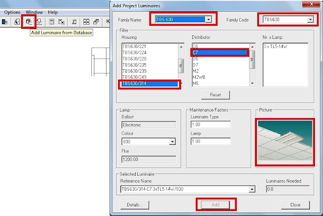
- In the Add Project Luminaires dialogue box, select following luminaires: Family Name TBS630, Family Code TBS630, Housing TBS630/314 and Light distributor C7-60.
- Do the same for other project luiminaires.
- Click OK.
Step#7: Defining the (calculation) grids
Now the (calculation) grids for the Working Plane, Floor, Curtain, Bureau, Conference
Table, Painting and Whiteboard will be defined.
Note: For this project the grid points do not have to be displayed in the 2D project overviews. Therefore, the 'Show Grid option' has to be disabled in the Project Options.
1- Excluding the grid points from the 2D project overviews
- Select Project Options from the Data menu.
- Select the 2D View tab.
- In the Show box, disable (no cross) Grids.
- Click OK.
2- Defining the grid for the Working Plane

- Select Grids from Data menu.
- Click Add in the Grids dialogue box.
- In the Add Grid dialogue box, enter the name of the grid, Name Working Plane
- In the Coupling box, select: Connected to None
- In the Definition box, enter the position of the grid points: Position
- A X = 0.30, Y = -3.60, Z = 0.80
- B X = 4.50, Y = -3.60, Z = 0.80
- C X = 0.30, Y = 3.60, Z = 0.80
- Number of Points in AB= 8 and in AC= 13
- Click OK.
3- Defining the grid for the Floor
- Click Add in the Grids dialogue box.
- In the Add Grid dialogue box, enter the name of the grid, Name Floor
- In the Coupling box, select: Connected to None
- In the Definition box, enter the position of the grid points: Position
- A X = 0.25, Y = -3.50, Z = 0.00
- B X = 4.50, Y = -3.50, Z = 0.00
- C X = 0.25, Y = 3.50, Z = 0.00
- Number of Points in AB= 9 and in AC= 15
- Click OK.
Note: The grid of the Floor is not connected to 'Working Plane', but user defined.
4- Defining the grid for the Curtain
- Click Add in the Grids dialogue box.
- In the Add Grid dialogue box, enter the name of the grid, Name Curtain
- In the Coupling box, select: Connected to None
- In the Definition box, enter the position of the grid points: Position
- A X = 0.00, Y = -3.30, Z = 0.25
- B X = 0.00, Y = 3.30, Z = 0.25
- C X = 0.00, Y = -3.30, Z = 2.50
- Number of Points in AB= 12 and in AC= 10
- Click OK.
5- Defining the grid for the Bureau
- Click Add in the Grids dialogue box.
- In the Add Grid dialogue box, enter the name of the grid, Name Bureau
- In the Coupling box, select: Connected to None
- In the Definition box, enter the position of the grid points: Position
- A X = 2.30, Y = -3.00, Z = 0.80
- B X = 3.10, Y = -3.00, Z = 0.80
- C X = 2.30, Y = -1.20, Z = 0.80
- Number of Points in AB= 5 and in AC= 10
- Click OK.
6- Defining the grid for the Conference Table
- Click Add in the Grids dialogue box.
- In the Add Grid dialogue box, enter the name of the grid, Name Conference Table
- In the Coupling box, select: Connected to None
- In the Definition box, enter the position of the grid points: Position
- A X = 1.00, Y = 0.70, Z = 0.80
- B X = 2.00, Y = 0.70, Z = 0.80
- C X = 1.00, Y = 2.90, Z = 0.80
- Number of Points in AB= 5 and in AC= 12
- Click OK.
7- Defining the grid for the Painting
- Click Add in the Grids dialogue box.
- In the Add Grid dialogue box, enter the name of the grid Name Painting
- In the Coupling box, select: Connected to None
- In the Definition box, enter the position of the grid points: Position
- A X = 1.10, Y = -3.70, Z = 1.50
- B X = 1.70, Y = -3.70, Z = 1.50
- C X = 1.10, Y = -3.70, Z = 1.90
- Number of Points in AB= 5 and in AC= 5
- Click OK.
8- Defining the grid for the Whiteboard
- Click Add in the Grids dialogue box.
- In the Add Grid dialogue box, enter the name of the grid, Name Whiteboard
- In the Coupling box, select: Connected to None
- In the Definition box, enter the position of the grid points: Position
- A X = 1.80, Y = 3.70, Z = 1.20
- B X = 3.00, Y = 3.70, Z = 1.20
- C X = 1.80, Y = 3.70, Z = 2.10
- Number of Points in AB= 8 and in AC= 7
- Click OK, then Close.
After defining all grids, the grids window will have the following grids as follws:

In the next article, I will continue explaining example#3 for lighting design by using CalcuLux indoor software. Please, keep following.

No comments:
Post a Comment