
In the previous topic "Electrical Single Line Diagram - Part One", I listed the types of electrical diagrams that any electrical engineer can deal with. These types were as follows:
- Block Diagrams
- Schematic Diagrams
- Pictorial Diagrams
- Wiring Diagrams
- Single-Line Diagrams
- Other types of diagrams
Today, I will continue explaining other types of electrical diagrams as follows.
5- Single Line Diagram
The single line diagram is circuit diagram where "one-line" is shown to represent three phases of a three phase power system. In addition to showing the ratings and size of electrical equipment and circuit conductors, a properly drawn one-line diagram will also show an electrically correct distribution of power with respect to current flow from the power source to the downstream loads or panelboards.
Importance of Single Line Diagrams:
- It is used to analyze a building's electrical system,
- Building maintenance staff and electricians rely on one-line diagrams to show them the way around the electrical system,
- Inaccuracy in this documentation and failure to update one-line diagrams on a regular basis as electrical systems invariably grow over time often results in increased down time when system failures occur,
- Facility supervisors may use the info found in single-line diagrams to greatly enhance the performance of service activities,
- The single line diagram offers several benefits to the facility it outlines, especially: identification of possible problem places, improved safety conformity, and enhanced staff safety.
Construction of Single Line Diagrams:
- Single-line diagram is a simplified notation for representing a three-phase power system; Instead of representing each of three phases with a separate line or terminal, only one conductor is represented.
- Electrical elements such as circuit breakers, transformers, capacitors, bus bars, and conductors are shown by standardized schematic symbols.
- Elements on the diagram do not represent the physical size or location of the electrical equipment.
- On one-line power diagrams, components are usually arranged in order of decreasing voltage levels. The highest voltage component is shown at the top right of the drawing. In order to find out how power is supplied to a component, start at the component and trace the flow of power backwards through the drawing. This method will be most useful in locating the correct circuit breaker to isolate a component for maintenance
- You can read the single line diagram from the top to the bottom or from left to right of the diagram.
The one-line diagram provides the following information:

- Manufacturers type designations, and ratings of devices.
- Ratios of current and power transformers, taps to be used in multi-ratio transformers, and connections of double-ratio transformers.
- Rating connections of wye and delta power transformer windings
- Circuit breaker ratings in volts and amperes.
- The interrupting rating, type, and number of trip coils on circuit breakers.
- Switch and fuse ratings in volts and amperes.
- Function of relays.
- The sizes, type, and number of incoming and outgoing cables.
- The voltage, phase, and frequency of incoming and outgoing circuits. The available short circuit and ground currents of the power company system, and type of ground used.
- Metered points and type of metering.
- The amount of the load on all feeders.
Develop a single line diagram (as per IEEE and ANSI)
to be familiar with the method of single line development by ANSI and IEEE you should know the following items:
A- Abbreviations used for Principal Meters:
 |
| Fig (1): Abbreviations used for Principal Meters |
The abbreviations used for principal meters, instruments, and other devices (not including relaying, which is listed in Fig. 2) are listed in fig.1 above.
B- ANSI Standard Device Function Numbers
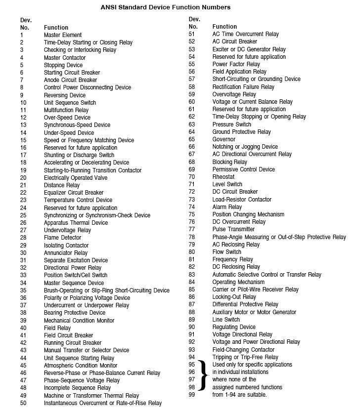 |
| Fig (2): ANSI Standard Device Function Numbers |
- Each device in an automatic switching equipment has a device function number (see fig.2) which is placed adjacent to or within the device symbol on all wiring diagrams and arrangement drawings so that its function and operation may be readily identified.
- These numbers are based on a system which was adopted as standard for Automatic Switchgear by the American National Standards Institute (ANSI C37.2).
Three steps are used in producing a one-line diagram (as per IEEE and ANSI):
- The preliminary one-Line diagram,
- The partially developed diagram,
- The developed diagram.
1- Preliminary One-Line Diagram
 |
| Fig (3): Preliminary One-Line Diagram |
on the The preliminary one-Line diagram (example as Fig.3), the designer must show the following:
- System voltage and major component ratings.
- Major medium-voltage cable lengths, sizes, and construction. (Not shown in example.) Approximate number and ratings of all motors.
- Supply system available short-circuit capability in symmetrical MVA (plus X/R ratio) or per unit R+jX (on a given basis).
Using data on the one-line diagram, the designer will perform some short circuit calculations as follows:
- Compare the calculated “first cycle” (Momentary) asymmetrical current duty with the close and latch circuit breaker capability.
- Compare the calculated “1-1/2 to 4-cycle” (interrupting) current duty with the circuit breaker symmetrical interrupting capability. (as per ANSI C37.010: Application Guide for AC High-Voltage Circuit Breakers Rated on a Symmetrical Current Basis).
- Determine the applicable circuit breaker ratings.
- Compare the feeder cable short-circuit heating limit with the maximum available short circuit current time Kt times Ko. (See IEEE 242-1975: IEEE Recommended Practice for Protection and Coordination of Industrial and Commercial Power Systems).
Note:
the calculations performed in accordance with Reference to (ANSI C37.010: Application Guide for AC High-Voltage Circuit Breakers Rated on a Symmetrical Current Basis) determine only medium and high-voltage circuit breaker ratings.
2- Partially Developed One-Line Diagram
- Perform short-circuit studies to determine relay operating currents in accordance with procedures outlined in IEEE 357-1973: IEEE Guide for Protective Relaying of Utility-Consumer Interconnections).
- For other than power circuit breakers, refer to the appropriate ANSI standard for short-circuit calculation procedure.
2- Partially Developed One-Line Diagram
 |
| Fig (4): Partially Developed One-Line Diagram |
Using the sample system in Fig.3 , a partially developed one-line diagram is shown in Fig.4.
On the Partially Developed One-Line Diagram, the designer should:
- Show the results of the short-circuit calculations performed, using the preliminary one-line diagram and selected circuit breaker ratings.
- Show ratings selected for external devices, such as grounding resistors, control power transformers, considering the type of protective relaying instrumentation and metering required.
- Select tentative current transformer (CT) ratios in considering the maximum transformer rating, motor ratings, and ampacity of the circuits involved.
- Locate current transformers and voltage transformers, considering the type of protective relaying instrumentation and metering required.
3- Developed One-Line Diagram
 |
| Fig (5): Developed One-Line Diagram |
A developed one-line diagram (for the system example in Fig.3) is shown in Fig.5.
In addition to the information shown on the partially developed one-line diagram, the Designer should:
- Show all relaying, instrumentation, and metering.
- Select relaying, instrumentation, and metering.
- Confirm the selection of relay ratings and characteristics by performing a complete system short-circuit and coordination study. As per the following IEEE Standards:
- 141-1969: Electric Power Distribution for Industrial Plants.
- 142-1972: IEEE Recommended Practice for Grounding of Industrial and Commercial Power Systems.
- 241-1974: IEEE Recommended Practice for Electrical Power Systems in Commercial Buildings.
- 242-1975: IEEE Recommended Practice for Protection and Coordination of Industrial and Commercial Power Systems.
- Include in the study an examination of all circuits for compliance with applicable local and national codes.
- Verify that all circuit conductors are applied within the conductor short-circuit heating limit. (As per IEEE 242-1975: IEEE Recommended Practice for Protection and Coordination of Industrial and Commercial Power Systems.)
In the next Topic, I will explain other types of Electrical Diagrams and Electrical diagram Symbols. So, please keep following.

for this part :
ReplyDeleteThree steps are used in producing a one-line diagram (as per IEEE and ANSI):
The preliminary one-Line diagram,
The partially developed diagram,
The developed diagram.
which IEEE, ANSI do you use?
thanks
ReplyDelete