Lighting Design by Using Quick Estimate Charts


I indicated before in our course  Advanced Course for Lighting Design - Level I ", that we can design interior lighting by using any method from the following three ones: 

  1. The Zonal Cavity (Lumen) method, 
  2. Point by point method, 
  3. Watt per square feet method. 

You can review the following previous articles for more information and good following: 


Today I will explain the Lighting Design by using quick estimate charts and IES Recommended lighting Levels 
as follows. 


Lighting Design by Using Quick Estimate Charts


  • You can consider this method as a forth method for lighting design, lighting designers can use manufacturers’ “quick estimate charts” as a means of estimating illuminance based on typical spacing criteria for a concept. 
  • It can be used to Estimate average illuminance for small to large rooms and to Estimate illuminance at a point. 
  • Caution is necessary using quick estimate charts when the spatial characteristics (room size and finish) or lamp selection varies from the manufacturer’s basis for the actual charts. 
  • Use of quick estimate charts provide the designer with a place to begin exploring a concept as preliminary estimates of lighting performance rather than a final performance estimate. 


How to use Quick-Estimate Illumination Chart


For explanation purpose, I will use the Quick-Estimate Illumination Chart from Manufacturer “Appleton” for high pressure sodium lamps 400W H.P.S. (Fig.1) and for metal halide lamp 400W M.H. (Fig.2) As follows:


Fig.1


Fig.2


Step#1:  Refer to "Quick-Estimate Illumination Chart" for the lamp type and wattage to be used.

Step#2: Determine "room" size of area to be lighted. "Small Room" is 2500 Sq. Ft. or less. "Medium Room" is 2500 Sq. Ft. thru 10,000 Sq. Ft. A "Large Room” is 10,000 Sq. Ft. or more.

Step#3: Find level of light (foot candles) required in vertical column of figures at left of chart. Then follow horizontal line (real or interpolated) to right until it intersects with "Arc" or selected "room size". Come directly down from point of intersection to horizontal line of number "Square Feet Per Luminaire".
The resulting number (real or interpolated) is the "number of square feet" one fixture will illuminate to the selected average maintained footcandle level when mounted in conjunction with other units in the installation. 

Step#4: Divide number of total square feet in project by "number of square feet per luminaire" to get number of units required.

Step#5: Take square root of resulting "number of square feet per luminaire" number to determine spacing between units


Example#1 :

We have 15,000 Sq. Ft. interior space ”room” area, estimate the number of luminaires that can be used for this space By using the Quick-Estimate Illumination Chart from Manufacturer “Appleton” for high pressure sodium lamps 400W H.P.S. at fig (3) in below.


Fig.3


Answer: 

Step#1: Refer to the Quick-Estimate Illumination Chart from Manufacturer “Appleton” for high pressure sodium lamps 400W H.P.S. at fig (3) above. 

Step#2: The room size = 15,000 Sq. Ft. , so we will use the large room curve.

Step#3: The required level of light for this space is 150 fc (this is for explanation purpose only),

  • Find the 150 fc value on the vertical column, 
  • Make a horizontal line from 150 fc value to intersect with the large room curve, 
  • Come directly down from point of intersection to horizontal line of number "Square Feet Per Luminaire". 

  • So, number of square feet per this luminaire = 170 Sq. Ft. / luminaire. 


Step#4: The number of luminaires = 17,000 / 170 = 100 luminaire.

Step#5: Spacing between luminaire = sq. root of 170 = 13 feet.


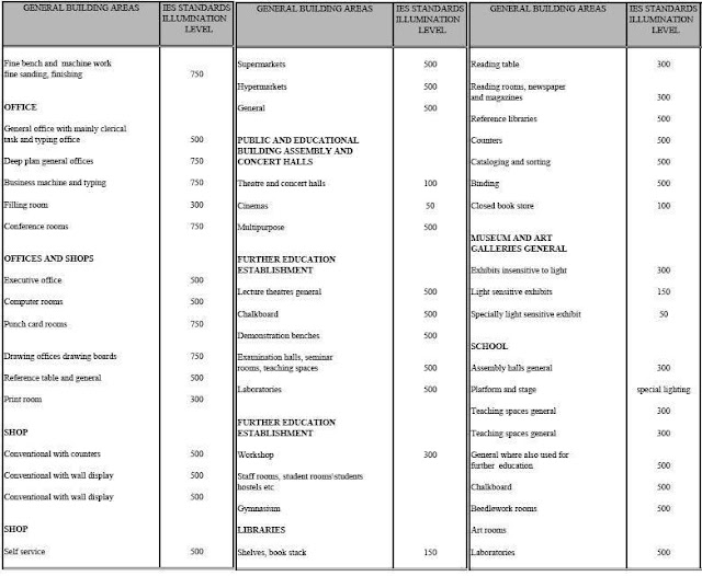
IES recommended foot candles Levels:


The IES recommended foot candles Levels are listed in the below table: 


IES recommended LUX Levels:


The IES recommended foot candles Levels are listed in the below tables:


In the next article, I will explain The Lighting Design for Normal Activities. Please keep following.


Watt Per Square Feet Method


I indicted before in our course Advanced Course for Lighting Design - Level I ", that we can design interior lighting by using any method from the following three ones: 

  1. The Zonal Cavity (Lumen) method,
  2. Point by point method,
  3. Watt per square feet method.

I explained the first and second method in the following articles: 


You can review the following previous articles for more information and good following:


Today I will explain the third method for lighting design which is “ Watt per square feet method” as follows. 


Third: Watt per square feet method (as per ASHRAE/ANSI/IESNA 90.1)


We have two cases for lighting design by using Watt per square feet method which are: 

  1. Space-by-Space Method (functional area method), 
  2. The Whole Building Method. 

1- Space-by-Space Method (functional area method)


Space by Space Method

In the Space-by-Space Method, the building will be divided into different space based on its function like offices, conference halls, corridors and lobbies, shops, parking areas, workshops and etc (see fig.1). The lighting power density (LPD) in (W/ft2) or/and (VA/ft2) is prescribed for these different spaces, these lighting power densities (LPDs) in addition to spaces area will be used to estimate the preliminary lighting load of this building as described in below.


Usage conditions of Space-by-Space Method


  • The Space-by-Space Method is used only for individual spaces in the building. 
  • The Space-by-Space Method may be used for any building or portion of a building. 


Area Measurement in space by space method

The square footage is measured from the outside surface of exterior walls to the centerline of walls between interior partitions of the spaces. The sum of the Gross Interior Area equals the total Gross Area of the building.


Method of estimation by using Space-by-Space Method


1- Divide the building into different space based on its function (for example, office, storage, mechanical, and corridor). 


2- Calculate the gross interior area of each space.

3- Determine the Lighting power density in (W/ft2) or/and (VA/ft2) for this space from the following table(as per ASHRAE/ANSI/IESNA 90.1): 


4- Consider requirements for supplementary lighting (for example, floodlighting, security lighting, and special task lighting).


5- Multiply the gross interior area of the space by the assigned Lighting load density to get the estimated lighting electrical load for this space.


Example#1:


For a high-rise office building with shopping arcade, a 10-story building (12 floors) with a floor area of approx. 25 m x 60 m.

There is a car park for customers in front of the building, the access way to the parking garage (levels -1 to -3 for employees) and a fountain (80 m x 20 m).

Real floor area approx. 1350 m2 (14 levels + technical equipment on roof level).

Floor heights of levels 00 to +10: 4 m, levels -1 to -3: 3 m
Calculate Preliminary lighting power for this building. 


Answer: 


2- The Whole Building Method 


The Whole Building Method is used for buildings, to some extent, bigger than that can be handled by the Space by space method, although it is easier than the Space by space method as you estimate the electrical load based on the activity of the whole building unlike the Space by space method which need dividing the building into multi areas with different activities.


Comparison between space-by-space and building type methods

  • Lighting Power densities (LPDs) under the two methods are similar for buildings with typical space distributions, but may vary depending on the space distributions in particular buildings. 
  • In general The Whole Building Method is easier to use than the Space-by-Space Method, but the Space-by-Space Method offers greater flexibility. 
  • In addition, the Space-by-Space Method allows the use of the Additional Interior Lighting Power Allowance for certain specific uses. 


Usage conditions of The Whole Building Method


The Whole Building Method may be used only for:

  • An entire building (using the primary occupancy), or; 
  • Single, independent, and separate occupancies in a multi-occupancy building. 


Area Measurement in The Whole Building Method


Total Gross Area will be used in The Whole Building Method and the square footage is measured from the outside surface of exterior walls, or from the outside surface of exterior walls to the centerline of walls between building types.


Method of estimation by using The Whole Building Method


1- Calculate the total Gross Area for the building; 

2- Determine the building type/usage (use a reasonable equivalent if the specific building type is not listed);

3- Determine the load density in (W/ft2) or/and (VA/ft2) for that building from the following Table:


4- Multiply the total gross area of the building by the assigned Lighting power density to get the estimated lighting power loads for this building.


5- Take into your consideration the following points:

Consider requirements for supplementary lighting (for example, floodlighting, security lighting, and special task lighting).


Example#2:


(4) floors office building with a floor area 2000 SF, calculate the total preliminary electrical load for the transformer(s) feeding this building By using The above tables from ASHRAE and IEEE.


Answer: 


The total gross area of the building = 2000 x 4 = 8000 SF

The building type/usage is Office

From above ASHRAE and IEEE tables, the load densities will be as follows:

Lighting = 1 W/SF

The subtotals estimated electrical loads will be as follows:

Lighting power load = 1 W/SF x 8000 = 8000 Watt


Conversions between different units of lighting quantities:


You can use the following table to convert between different units of lighting quantities as follows: 


In the next article, I will explain the quick estimate charts and complete lighting design examples. Please, keep following.


Watt Per Square Feet Method


I indicted before in our course, that we can design interior lighting by using any method from the following three ones:
The Zonal Cavity (Lumen) method
Point by point method
Watt per square feet method


I explained the first and second method in the following articles:

You can review the following previous articles for more information and good following:


Today I will explain the third method for lighting design which is “Watt per square feet method” as follows.


Third: Watt per square feet method (as per ASHRAE/ANSI/IESNA 90.1)

We have two cases for lighting design by using Watt per square feet method which are:

Space-by-Space Method (functional area method),
The Whole Building Method.


1- Space-by-Space Method (functional area method)

In the Space-by-Space Method, the building will be divided into different space based on its function like offices, conference halls, corridors and lobbies, shops, parking areas, workshops and etc (see fig.1).  The lighting power density (LPD) in (W/ft2) or/and (VA/ft2) is prescribed for these different spaces, these lighting power densities (LPDs) in addition to spaces area will be used to estimate the preliminary lighting load of this building as described in below.

Usage conditions of Space-by-Space Method

The Space-by-Space Method is used only for individual spaces in the building.
The Space-by-Space Method may be used for any building or portion of a building.

Area Measurement in space by space method

The square footage is measured from the outside surface of exterior walls to the centerline of walls between interior partitions of the spaces. The sum of the Gross Interior Area equals the total Gross Area of the building.

Method of estimation by using Space-by-Space Method


- Divide the building into different space based on its function (for example, office, storage, mechanical, and corridor).
Calculate the gross interior area of each space.

Determine the Lighting power density in (W/ft2) or/and (VA/ft2) for this space from the following table(as per ASHRAE/ANSI/IESNA 90.1):

Consider requirements for supplementary lighting (for example, floodlighting, security lighting, and special task lighting).

Multiply the gross interior area of the space by the assigned Lighting load density to get the estimated lighting electrical load for this space.

Example#1:

For a high-rise office building with shopping arcade, a 10-story building (12 floors) with a floor area of approx. 25 m x 60 m.
There is a car park for customers in front of the building, the access way to the parking garage (levels -1 to -3 for employees) and a fountain (80 m x 20 m).
Real floor area approx. 1350 m2 (14 levels + technical equipment on roof level).
Floor heights of levels 00 to +10: 4 m, levels -1 to -3: 3 m

Calculate Preliminary lighting power for this building.


Answer:


Space
Area (sqft)
Load Density
Watt/sqft
Estimated lighting Load For Space
Parking Garage / Utilities Areas (Incl. Roof Area)
46,391
0.2
9,278
watt
Shopping Center / Bank
14,701
1.55
22,787
watt
Offices
14,701
1.13
16,612
watt
Total Estimated Lighting load
48,677
watt

Application Of Cos Phi = 0.85
57,267
watt

Application Of Load Level = 70%
81,810
watt

Preliminary lighting load
81.81
KW


2- The Whole Building Method

The Whole Building Method is used for buildings, to some extent, bigger than that can be handled by the Space by space method, although it is easier than the Space by space method as you estimate the electrical load based on the activity of the whole building unlike the Space by space method which need dividing the building into multi areas with different activities. 

Comparison between space-by-space and building type methods

Lighting Power densities (LPDs) under the two methods are similar for buildings with typical space distributions, but may vary depending on the space distributions in particular buildings.
In general The Whole Building Method is easier to use than the Space-by-Space Method, but the Space-by-Space Method offers greater flexibility.
 In addition, the Space-by-Space Method allows the use of the Additional Interior Lighting Power Allowance for certain specific uses.


Usage conditions of The Whole Building Method
The Whole Building Method may be used only for:

An entire building (using the primary occupancy), or;
Single, independent, and separate occupancies in a multi-occupancy building.

Area Measurement in The Whole Building Method
Total Gross Area will be used in The Whole Building Method and the square footage is measured from the outside surface of exterior walls, or from the outside surface of exterior walls to the centerline of walls between building types.

Method of estimation by using The Whole Building Method


Calculate the total Gross Area for the building;
Determine the building type/usage (use a reasonable equivalent if the specific building type is not listed);
Determine the load density in (W/ft2) or/and (VA/ft2) for that building from the following Table:

Multiply the total gross area of the building by the assigned Lighting power density to get the estimated lighting power loads for this building.

Take into your consideration the following points:
Consider requirements for supplementary lighting (for example, floodlighting, security lighting, and special task lighting).


Example#2:
 (4) floors office building with a floor area 2000 SF, calculate the total preliminary electrical load for the transformer(s) feeding this building By using The following tables from ASHRAE and IEEE.

Answer:
The total gross area of the building = 2000 x 4 = 8000 SF
The building type/usage is Office
From above ASHRAE and IEEE tables, the load densities will be as follows:
 Lighting = 1 W/SF
The subtotals estimated electrical loads will be as follows:
Lighting power load = 1 W/SF x 8000 = 8000 Watt


Conversions between different units of lighting quantities:

You can use the following table to convert between different units of lighting quantities as follows:


In the next article, I will explain the quick estimate charts and complete lighting design examples. Please, keep following.

Point by Point Method for Lighting Design


I indicted before in our course Advanced Course for Lighting Design - Level I ",  that we can design interior lighting by using any method from the following three ones: 

  1. The Zonal Cavity (Lumen) method,
  2. Point by point method,
  3. Watt per square feet method.


Today I will explain the second method for lighting design which is “ point by point method” as follows .


You can review the following previous articles for more information and good following:


Second: Point by Point Method


The first method for lighting design which was Zonal cavity (Lumen) method is used to calculate average illuminance for places having uniform lighting distrbution, but this method , for example, can’t answer the following questions:

  1. What is the illuminance on a wall display from a spotlight aimed at the display? 
  2. How much light is striking a point on the façade of a building or in a parking lot from a floodlight? 

The only way for getting answers for above questions is by applying point to point method for lighting design. 

Three Factors must be considered for applying the Point by point method: 

  1. Luminous intensity,
  2. Distance,
  3. Orientation of the surface.


1- Luminous Intensity (I)


The luminous intensity (candelas) is the strength (intensity) of the light produced in a specific direction.

Or

It is Luminous Flux in a certain direction, radiated per unit of solid angle.

It’s unit is candela.


The luminous intensity of any light source is compiled graphically into diagrams known as candela or candlepower distribution curves. Both polar and Cartesian graphs are used within the lighting industry for this purpose. This information is also available in numeric tabular form.


Candlepower Distribution Curve


A curve, generally polar, represents the variation of luminous intensity of a lamp or luminaire in a plane through the light center.

The luminous intensity (I) is determined using the photometric data for the specific luminaire used and the angular relationship between the luminaire aiming direction and the direction from the luminaire to the calculation point. 


There are three types of Candlepower Distribution Curve as follows: 

A- Rotational symmetrical 

Light distribution same in all planes. Usually Circular or ‘Bowl shaped’ luminaire


Rotational symmetrical


B- Planar symmetrical 


Luminaire distribution is confined to two vertical planes separately. Typical distribution for Fluorescent Lamp luminaires and Road Lighting


Planar symmetrical 


C- Asymmetrical 


Asymmetry present in one of the Planes of measurement.


 Asymmetrical 


2- Distance


Distance between a surface and the source affects the illuminance (luminous flux per unit of area) striking that surface

Surface of a given area that is closer to the source captures a larger portion of the flux in the cone than a surface of the same given area that is further away

Considering the luminous intensity as the luminous flux (lumens) leaving a source in a cone traveling in a specific direction, as the area increases the iluminance decreases while the luminous flux remains the same.


Inverse Square Law


It states that the cross-sectional area of the cone increases with the square of the distance from the source.

Therefore, the illuminance on this surface varies inversely with the square of the distance from the source.


Inverse Square Law states that


E = I/ d2 
Where: 

E = Illuminance on the surface

I = Luminous intensity of the source in the direction of the surface

d = Distance from the source to the surface


3- Orientation of the Surface


Surface orientation is included in the Inverse Square Law by adding a cos θ term: 


E = I/ d2 cos θ 

Where:
θ is the angle between the light ray coming from the source to the point, and a line that is perpendicular (normal) to the plane or surface on which the illuminance is being measured or calculated (see fig.). 

Example #1:

This example will consider the illuminance at a single point on a horizontal surface from a single luminaire straight down, given that:

  • D = 2.13 m 
  • θ = 15° 
  • LLF = 0.85 
  • I = 2200 candelas 

Calculate the illuminance level on this point.


Answer: 

Using the equation; 

E = I/ d2 x cos θ x LLFTOTAL

E = 2200 cd x cos 15° x 0.85 / 2.13 m2

E = 398 lux (maintained)


This tells us that 398 lux will strike the point in question directly from the luminaire and no reflected light is calculated. The answer is a maintained illuminance level since a light loss factor of 0.85 was included to account for the loss of light over time due to reduced lumen output of the lamp and dirt on the luminaire surfaces.


 point by point method calculations for different cases:


Based on the orientation of the surface, we have (5) cases in application of point to point method for lighting design as follows:

  1. Illuminance directly below the luminaire on a horizontal surface,
  2. Illuminance on horizontal surface but at angle to luminaire,
  3. Illuminance on vertical surface at angle to luminaire,
  4. Illuminanceon a tilted or sloped surface,
  5. Illuminanceon for multiple point source calculations.


1- Illuminance directly below the luminaire on a horizontal surface


2- Illuminance on horizontal surface but at angle to luminaire


3- Illuminance on vertical surface at angle to luminaire


4- Illuminanceon a tilted or sloped surface


5- Illuminanceon for multiple point source calculations (
Abney’s Law )


Example 2:


This example will consider the illuminance at a single point on a horizontal surface from two luminaires aimed straight down. An assumed LLF of 0.85 will be used and Luminaire #1 is the same in Example#1 and given that:

  • D1 = 2.13m,  θ1 = 15° 
  • D2 = 2.29m,  θ2 = 25° 
  • β1 = 15°,  I1 = 2200 cd 
  • β2 = 25°,  I2 = 2000 cd 
Calculate the illuminance level on this point. 


Answer: 

E1 = 398 lux (from previous calculation in example#1) 

E2 = 291 lux (same calculation method as E1)


Hence, Illumination from more than one source is added arithmetically
So, E total = E1 + E2 = 689 lux 


Example 3:

This example will consider the illuminance at multiple points on a vertical surface from a luminaire aimed at the surface. An assumed LLF of 0.85 will be used. The data for three points 1, 2& 3 are listed in below table:


Calculate the illuminance level on the three points.


Answer 
The luminaire is now aimed at the vertical surface so β is no longer measured from straight down, and β and θ are no longer equal. 

Illuminance is calculated using the same equation as the prior examples , the results are listed in below table


Notes for example#3: 


  • In Table 1, illuminance at point 2 is greater than at point 1 and illuminance at point 3 is the least. This is because the distance at point 2 is less than point 1 and the angle theta (θ ) at point 2 is less than at point 1, despite the fact that the intensity in that direction is less. 
  • Similar reasoning can be used with regard to point 3. 
  • These two factors cause the illuminance at point 2 to be greater than the illuminance at point 3. 


Limits for using point by point method:


  • Maximum physical dimension of the surface under design is not larger than 1/5th the mounting height above the evaluation point. 
  • Does not apply to a surface of infinite length. 


In the next Article, I will explain the third method for lighting design “Watt per square feet method”. Please, keep following.