
In the previous Topic “The
Electrical Distribution Architecture – Part One “ , I list the Tasks required for application of Electrical Distribution architecture design process , they were:
- Assigning of electrical installation characteristics,
- Assigning of Technological characteristics,
- Using Architecture assessment criteria,
- Step (1): Choice of distribution architecture fundamentals,
- Step (2): choice of architecture details,
- Step (3): choice of equipment,
- Recommendations for architecture optimization.
And I began explaining the first task: Assigning of electrical installation characteristics which include the following categories or possible values:
- Activity,
- Site topology,
- Layout latitude,
- Service reliability,
- Maintainability,
- Installation flexibility,
- Power demand,
- Load distribution,
- Power Interruption Sensitivity,
- Disturbance sensitivity,
- Disturbance capability of circuits,
- Other considerations or constraints.
Today, I will continue explaining other tasks for helping you to use Electrical Distribution architecture design process professionally.
2- Site topology
|
#
|
characteristic
|
Definition
|
choice
|
|
|
2
|
Site topology
|
Architectural
characteristic of the building(s), taking account of the number of buildings,
number of floors, and of the surface area of each floor.
|
|
1. Single storey building,(Low
Rise)
|
|
|
2.
Multi-storey building, ,(Low Rise)
|
|||
|
|
3. Multi-building site,
|
|||
|
|
4.
High-rise building
|
|||
Examples for Effect of Site Topology on design of Commercial Buildings:
1- Number of floors:
The number of floors will affect the electrical design as per the following rule:
The number of building floors must not exceed the max. Number of floors for the proposed Electrical Distribution architecture calculated by equation#1
If:
Max. Side length of the building = a (in meter)
One Floor area A = a2 (in square meter)
Height per floor = h (in meter)
Then:
Max. Number of floors for the proposed Electrical Distribution architecture (i) ≤ (100 – 2a) / h (equation#1)
If the number of floors exceed the max. Number of floors for the proposed Electrical Distribution architecture (i) calculated by equation#1, then we must use other types of the proposed Electrical Distribution architecture.
Notes:
- All buildings have number of floors ≤ 4 are low rise buildings.
- All buildings have number of floors > 4 are high rise buildings.
There is max. Number of floors for each proposed Electrical Distribution architecture which be listed in the following table.
|
Module
|
Building type
|
Supply
|
Wiring /main route
|
Floors
|
Floor area
|
Total area
|
Power required
|
|
1
|
Low-rise building
|
1 supply section
|
Cable
|
≤ 4
|
2,500 m2
|
10,000 m2
|
1,000 – 2,000 kW
|
|
2
|
Low-rise building
|
2 supply section
|
Busbar
|
≤ 4
|
>2,000 m2
|
20,000 m2
|
> 2,000 KW
|
|
3
|
High-rise building
|
1 supply section, central
power supply
|
Cable
|
≤ 10
|
1,000 m2
|
≤ 10,000 m2
|
≤ 1800 kW
|
|
High-rise building
|
1 supply section, central
|
Busbar
|
≤ 10
|
1,000 m2
|
≤ 10,000 m2
|
≤ 1800 kW
|
|
|
4
|
High-rise building
|
1 supply section,
transformers at remote location
|
Cable
|
10 – 20
|
1,000 m2
|
≤ 20,000 m2
|
≥ 1,500 kW
|
|
5
|
High-rise building
|
1 supply section,
distributed
|
Cable
|
> 20
|
1,000 m2
|
> 20,000 m2
|
≥ 2,000 kW
|
|
High-rise building
|
1 supply section,
distributed
|
Busbar
|
> 20
|
1,000 m2
|
> 20,000 m2
|
≥ 2,000 kW
|
2- The surface area of each floor (see the above Table)
The surface area of each floor will affect the electrical design as follows:
- If the (Ground area / total area) of the building ≤ 2,500 m2 / 10,000 m2 use Low building , Type 1: One Supply Section.
- If the floor area of the building > 2,000 m2 use Low building, type 2: Two supply sections.
- If the (Ground area / total area) of the building ≤ 1,000 m2 / 10,000 m2 use High-rise building, type 1&2 : Central power supply, cables/Busbars.
- If the (Ground area / total area) of the building ≤ 1,000 m2 / 20,000 m2 use High-rise building, type 3: Transformers at remote location.
- If the floor area of the building ≤ 1,000 m2 & the total area of the building > 20,000 m2 use High-rise building, type 4 & 5: Distributed supply, cables/Busbars.
For more information about effects Site Topology on Design, please review the following topics:
- Power system architectures for the commercial buildings – Part One
- Power system architectures for the commercial buildings – Part Two
- Power system architectures for the commercial buildings – Part Three
- Power system architectures for the commercial buildings – Part Four
- Power System Architectures for the Commercial Buildings – Part Five
- Comparison between Power system architectures for the commercial buildings
3- Layout latitude
|
#
|
characteristic
|
Definition
|
choice
|
|
|
3
|
Layout latitude
|
Characteristic taking
account of constraints in terms of the layout of the electrical equipment in
the building, these constraints are:
|
|
Low (≤ 2,000 m2): the position of the
electrical equipment is virtually imposed
|
|
1-aesthetics,
|
|
Medium (2,000 m2- 2,500 m2): the position of the
electrical equipment is partially imposed, to the detriment of the criteria
to be satisfied
|
||
|
2-accessibility,
|
||||
|
3-presence of dedicated locations,
|
||||
|
4-use of technical corridors (per floor),
|
|
High (> 2,500 m2): no constraints. The
position of the electrical equipment can be defined to best satisfy the
criteria.
|
||
|
5-use of technical ducts (vertical).
|
||||
Examples for Effect of Layout latitude on design of Commercial Buildings:
- if floor area (Layout Latitude) ≤ 2,500 m2, so there will be only one central equipment room per floor feed from the LVMD (Low Voltage Main Distribution switchgear).
- If floor area (Layout Latitude) > 2,000 m2, so there will be more than one (≥ 2) central equipment room per floor feed from the LVMD (Low Voltage Main Distribution switchgear).
- If floor area (Layout Latitude) between 2000m2 and 2,500 m2, the solution used will depend on the building layout shape as follows:
- Building layout Shape is one block, we can use central equipment room per floor.
- Building layout Shape is many combined blocks, we can use (≥ 2) central equipment room per floor.
Note:
the experience and professionalism of the electrical designer have a big effect on the selections and decisions taken regarding the proposed configuration of the Electrical Distribution architecture.
4- Service Reliability
The service reliability level is determined to be (minimal, standard and enhanced) based on the following factors:
The following table summarizes the effect of these factors on the required service reliability level and fig (1) represents the Configuration of Electrical Distribution Architecture in each case:
4- Service Reliability
|
#
|
characteristic
|
Definition
|
choice
|
||
|
4
|
Service reliability
|
The ability of a power
system to meet its supply function under stated conditions for a specified
period of time.
|
|
Minimum: this level of
service reliability implies risk of interruptions related to constraints that
are geographical (separate network, area distant from power production
centers), technical (overhead line, poorly meshed system), or economic
(insufficient maintenance, under-dimensioned generation).
|
|
|
|
Standard
|
||||
|
|
Enhanced: this level of
service reliability can be obtained by special measures taken to reduce the
probability of interruption (underground network, strong meshing, etc.)
|
||||
The service reliability level is determined to be (minimal, standard and enhanced) based on the following factors:
- The Activity importance of the building.
- The site topology of the building.
- The power demand of the building.
The following table summarizes the effect of these factors on the required service reliability level and fig (1) represents the Configuration of Electrical Distribution Architecture in each case:
Characteristic To
Consider
|
Configuration
Of Electrical
Distribution Architecture
|
||||
|
LV
|
MV
|
||||
|
Single-Line
|
Ring-Main
|
Duplicate Supply
|
Duplicate Supply With Double Busbars
|
||
|
Activity
|
Any
|
Any
|
Any
|
Hi-Tech, Sensitive Office, Health-Care
|
Any
|
|
Site Topology
|
Single Building
|
Single Building
|
Single Building
|
Single Building
|
Several Buildings
|
|
Power Demand
|
< 630kva
|
≤ 1250kva
|
≤ 2500kva
|
> 2500kva
|
> 2500kva
|
|
Service Reliability
|
Minimal
|
Minimal
|
Standard
|
Enhanced
|
Enhanced
|
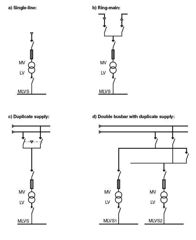 |
| Fig (1) |
In the next topic, I will continue explaining other Electrical installation characteristics, please keep following.

Hello there Eng. Ali,
ReplyDeleteCan you please elaborate pertaining to choice of Layout latitude? Position of electrical equipment, does this render the point where it is to be housed?
Thanks.