
In a previous Topic, “Electrical Load Classification and
Types”, I show that the electrical loads can be classified into various categories according to various factors; one of these factors is according to load function/usage as follows:
Third Classification: Electrical Load Classification According To Load Function
Third Classification: Electrical Load Classification According To Load Function
- Lighting Load.
- Appliances Load.
- Power Loads.
In the following previous Topics, I explained the first type; lighting load:
And I explained the second type; Appliances Load in the following previous topic:
And I showed that the third and last type of electrical loads according to the load function / usage is the power loads which can be divided to the following main loads:
- HVAC loads (Heating, Ventilation and Air Conditioning System Loads).
- Elevators, escalators and Moving walkways Loads (Transportation System Loads).
- Motor and Pumps Loads (Fire Fighting, Plumping, Irrigation Systems, Etc.).
Since this Course
EE-1 is for beginners in the electrical design field, I must explain in detail these loads or systems and indicate its construction, principals of operation and its different types. So, I explained the first type of power loads; HVAC Loads in the following previous topics:
Also, I explained the second item of power loads; Elevators, escalators and Moving walkways Loads (Transportation System Loads) in the following previous topics:
Introduction
- Electric motors defined as electromechanical devices that convert electrical energy to mechanical energy; they are the interface between the electrical and mechanical systems of a facility.
- Electric motors are an important part of any electrical system. They used throughout every manufacturing plant, office, and home consuming about 64% of all electricity generated.
- There are numerous ways to design a motor, thus there are many different types of motors and each type possess different operating characteristics (that will be listed later). Based on these characteristics the motor can be chosen for a specified application.
Principle of How Motors Work:
 |
| Principle of How Motors Work |
- Electrical current flowing in a loop of wire will produce a magnetic field across the loop.
- When this loop is surrounded by the field of another magnet, the loop will turn, producing a force (called torque) that results in mechanical motion
Motor basic parts:
Electric machines are classified into two categories D.C. and A.C. motors, the basic parts for each type will be different for each type as follows:
1- AC Motor Basic Parts:
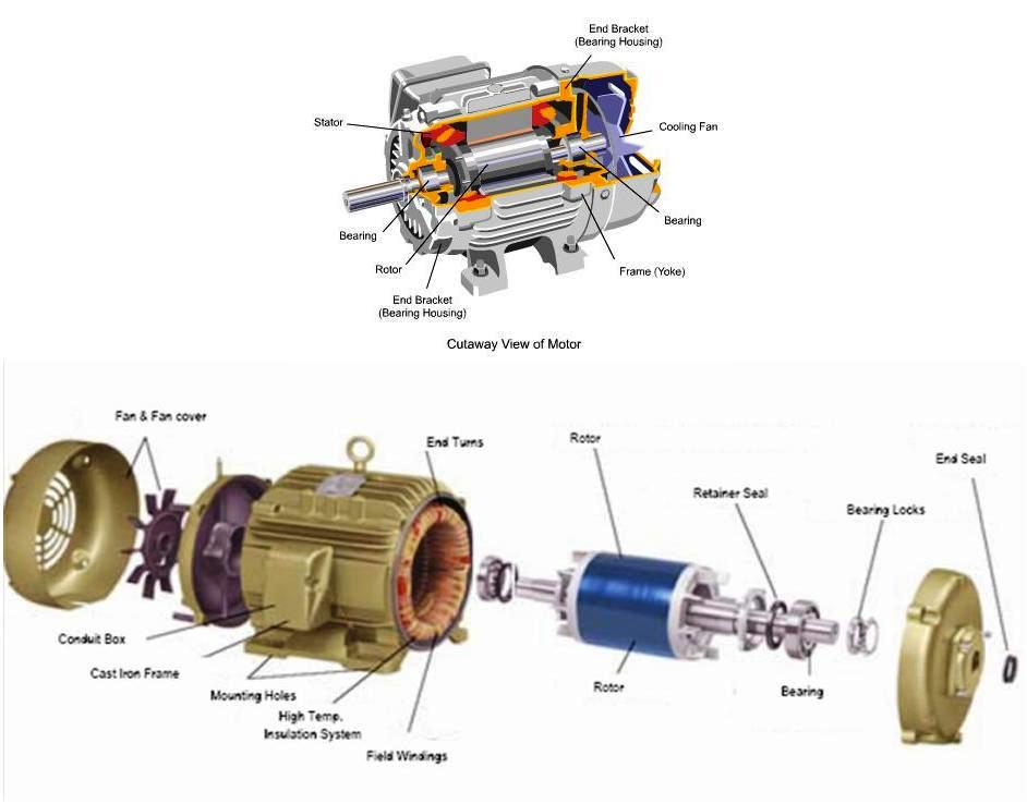 |
| AC Motor Basic Parts |
The basic parts for AC motors are as follows:
- Enclosure.
- Stator.
- Rotor.
- Bearings.
- Conduit Box.
- Eye Bolt.
1- Enclosure
 |
| Enclosure |
The enclosure consists of a frame (or yoke) and two end brackets (or bearing housings).
A motor's enclosure not only holds the motor's components together, it also protects the internal components from moisture and containments. The degree of protection depends on the enclosure type. In addition, the type of enclosure affects the motor's cooling. There are two categories of enclosures as follows:
- Open Enclosure.
- Totally enclosed Enclosure.
 |
| Open and Enclosed Types |
A- Open Enclosure
 |
| open drip proof (ODP) enclosure |
Open enclosures permit cooling air to flow through the motor. One type of open enclosure is the open drip proof (ODP) enclosure. This enclosure has vents that allow for air flow. Fan blades attached to the rotor move air through the motor when the rotor is turning. The vents are positioned so that liquids and solids falling from above at angles up to 15° from vertical cannot enter the interior of the motor when the motor is mounted on a horizontal surface. When the motor is mounted on a vertical surface, such as a wall or panel, a special cover may be needed. ODP enclosures should be used in environments free from contaminates.
B- Totally enclosed Enclosure
This category will include the following three types:
- Totally Enclosed Non-Ventilated Enclosure.
- Totally Enclosed Fan-Cooled Enclosure.
- Explosion-Proof Enclosure.
a- Totally Enclosed Non-Ventilated Enclosure (TENV)
 |
| Totally Enclosed Non-Ventilated Enclosure (TENV) |
In some applications, the air surrounding the motor contains corrosive or harmful elements which can damage the internal parts of a motor. A totally enclosed non-ventilated (TENV) motor enclosure limits the flow of air into the motor, but is not airtight. However, a seal at the point where the shaft passes through the housing prevents water, dust, and other foreign matter from entering the motor along the shaft.
Most TENV motors are fractional horsepower. However, integral horsepower TENV motors are used for special applications. The absence of ventilating openings means that all the heat from inside the motor must dissipate through the enclosure by conduction. These larger horsepower TENV motors have an enclosure that is heavily ribbed to help dissipate heat more quickly. TENV motors can be used indoors or outdoors.
b- Totally Enclosed Fan-Cooled Enclosure (TEFC)
 |
| Totally Enclosed Fan-Cooled Enclosure (TEFC) |
A totally enclosed fan-cooled (TEFC) motor is similar to a TENV motor, but has an external fan mounted opposite the drive end of the motor. The fan blows air over the motor's exterior for additional cooling. The fan is covered by a shroud to prevent anyone from touching it. TEFC motors can be used in dirty, moist, or mildly corrosive environments.
c- Explosion-Proof Enclosure (XP)
 |
| Explosion-Proof Enclosure (XP) |
- Hazardous duty applications are commonly found in chemical processing, mining, foundry, pulp and paper, waste management, and petrochemical industries. In these applications, motors have to comply with the strictest safety standards for the protection of life, machines and the environment. This often requires use of explosion proof (XP) motors.
- An XP motor is similar in appearance to a TEFC motor, however, most XP enclosures are cast iron.
- Division I locations normally have hazardous materials present in the atmosphere.
- Division II locations may have hazardous material present in the atmosphere under abnormal conditions.
- Locations defined as hazardous, are further defined by the class and group of hazard. For example,
- Class I, Groups A through D have gases or vapors present.
- Class II, Groups E, F, and G have flammable dust, such as coke or grain dust.
- Class III is not divided into groups. This class involves ignitable fibers and lint.
2- Stator
 |
| Stator |
The motor stator consists of two main parts:
A- Stator Core
The stator is the stationary part of the motor's electromagnetic circuit. The stator is electrical circuit that performs as electromagnet. The stator core is made up of many thin metal sheets, called laminations. Laminations are used to reduce energy losses that would result if a solid core were used.
B- Stator (Windings)
Stator laminations are stacked together forming a hollow cylinder. Coils of insulated wire are inserted into slots of the stator core.
When the assembled motor is in operation, the stator windings are connected directly to the power source. Each grouping of coils, together with the steel core it surrounds, becomes an electromagnet when current is applied. Electromagnetism is the basic principle behind motor operation.
3- Rotor
 |
| Rotor |
The rotor is the rotating part of the motor's electromagnetic circuit. Magnetic field from the stator induces an opposing magnetic field onto the rotor causing the rotor to “push” away from the stator field.
There are a lot of rotor types like Squirrel cage rotor and wound rotor, they will be explained later.
4- Bearings
 |
Bearings, mounted on the shaft, support the rotor and allow it to turn. Not all bearings are suitable for every application; a universal, all-purpose bearing does not exist. The choice of bearing arrangement is based on the following qualities:
The size of the bearing to be used is initially selected on the basis of its load carrying capacity, in relation to the load to be carried, and the requirements regarding its life and reliability.
Other factors must also be taken into consideration, such as operating temperature, dirty and dusty environmental conditions, and vibration and shocks affecting bearings in running and resting conditions.
Bearings Types:
There are many types of bearings on the market, each with different characteristics and different uses, these types are as follows:
A- Deep groove ball bearings
- Load carrying capacity in the axial and radial direction.
- Overspeed and duration.
- Rotating speed.
- Bearing life.
The size of the bearing to be used is initially selected on the basis of its load carrying capacity, in relation to the load to be carried, and the requirements regarding its life and reliability.
Other factors must also be taken into consideration, such as operating temperature, dirty and dusty environmental conditions, and vibration and shocks affecting bearings in running and resting conditions.
Bearings Types:
There are many types of bearings on the market, each with different characteristics and different uses, these types are as follows:
A- Deep groove ball bearings

Deep groove ball bearings are the most common type of bearing, and can handle both radial and thrust loads. Due to their low-frictional torque, they are suitable for high speeds.
In a ball bearing, the load is transmitted from the outer race to the ball and from the ball to the inner race.
Since the ball is a sphere, it only contacts the inner and outer race at a very small point, which helps it to spin very smoothly. This also means that there is not very much contact area holding the load, so if the bearing is overloaded, the balls can deform, ruining the bearing.
B- Cylindrical roller bearings

These roller bearings are used in applications where they must hold heavy radial loads. In the roller bearing, the roller is a cylinder, so the contact between the inner and outer race is not a point but a line. This spreads the load out over a larger area, allowing the bearing to handle much greater radial loads than a ball bearing.
However, this type of bearing is not designed to handle much thrust loading.
C- Angular contact ball bearings

Angular Contact ball bearings have raceways in the inner and outer rings which are displaced with respect to each other in the direction of the bearing axis. This means that they are suitable for the accommodation of combined loads such as simultaneously acting radial and axial loads in vertical machines.
D- Spherical roller thrust bearing

In Spherical Roller thrust bearings, the load is transmitted from one raceway to the other at an angle to the bearing axis. They are suitable for the accommodation of high axial loads in addition to simultaneously acting small radial loads. Spherical roller thrust bearings are also self-aligning.
E- Sleeve Bearings

Sleeve bearings have no moving parts, they rely on a thin film of oil to reduce friction and allow the motor shaft to turn freely. This film of oil is critical to the life of a sleeve bearing.
When properly lubricated, there is actually no physical contact between the bearing and the shaft. If for some reason the oil film breaks down, metal-to-metal contact between the shaft and the bearing will cause the bearing to wear very quickly and soon fail
Sleeve bearings are often chosen because of their relatively quiet operation and lower cost compared to ball bearings.
Sleeve bearings can be divided to:
a- Flange mounted sleeve bearings are used for machines with a shaft height of up to 1120mm. Machines with bearings of this type are quick and easy to align. The air gap between stator and rotor comes from the factory already adjusted, and does not need any further adjustment on site during installation.
b- Foot mounted sleeve bearings are mounted on a pedestal. The pedestal can either be integrated in the stator frame, or can be mounted separately. If it is integrated with the stator frame it is easy and fast to align.
5- Conduit Box
 |
| Conduit Box |
Point of connection of electrical power to the motor’s stator windings.
6- Eye Bolt
 |
| Eye Bolt |
Used to lift heavy motors with a hoist or crane to prevent motor damage.
2- DC Motor Basic Parts:
 |
| DC Motor Basic Parts |
The basic parts for DC motors are as follows:
1- Stator
The stator carries the field winding and Poles. The stator together with the rotor constitutes the magnetic circuit or core of the machine. It is a hollow cylinder.
2- Rotor
It carries the armature winding. The armature is the load carrying member. The rotor is cylindrical in shape.
3- Armature Winding
This winding rotates in the magnetic field set up at the stationary winding (Field winding). It is the load carrying member mounted on the rotor. An armature winding is a continuous winding; that is, it has no beginning or end. It is composed of a number of coils in series.
4- Field Winding
This is an exciting system which may be an electrical winding or a permanent magnet and which is located on the stator.
Note: DC Motors are generally classified by how their Armature & Field windings are connected to their DC power supply.
5- Commutator
 |
| Commutator Winding |
The coils on the armature are terminated and interconnected through the commutator which comprised of a number of bars or commutator segments which are insulated from each other. The commutator rotates with the rotor and serves to rectify the induced voltage and the current in the armature both of which are A.C.
6- Brushes
 |
| Brushes |
These are conducting carbon graphite spring loaded to ride on the commutator and act as interface between the external circuit and the armature winding.
7- Poles
 |
| Poles |
The field winding is placed in poles, the number of which is determined by the voltage and current ratings of the machine.
8- Slot/Teeth
For mechanical support, protection from abrasion, and further electrical insulation, non-conducting slot liners are often wedged between the coils and the slot walls. The magnetic material between the slots is called teeth.
9- Motor Housing
The motor housing supports the iron core, the brushes and the bearings.
In the next Topic, I will explain the Electrical Motors types. So, please keep following.
Note: these topics about Motors in this course EE-1: Beginner's electrical design course is an introduction only for beginners to know general basic information about Motors and Pumps as a type of Power loads. But in other levels of our electrical design courses, we will show and explain in detail the Motor and Pumps Loads calculations.

Your explanation is about the electrical motor and its type’s is clear. Each component in that work explanation is useful specially the ball bearings types and its uses.
ReplyDeleteVery nice.....explain action by exploded view is very good.....
ReplyDeleteExplanation part was good but if you add a graphical video about each part and explain the working and building of motor it would be excellent
ReplyDeleteI learn many thing from here. Tnxx for all
ReplyDeleteAll those topics are properly explained. I like it
ReplyDeleteTHANK U
ReplyDeleteVery very helpful. thank you Sr.
ReplyDeletethanks very much,really helped me in doing my assaingment..... thanks
ReplyDeletevery nice explanation
ReplyDeletenice and helpful too. thanks.
ReplyDeletecourse exposed is very good, I improved my knowledge in the AC motor
ReplyDeleteIt is noble to provide free, and concise educational information, and it is always welcome by the public! Thank you for your eleemosynary contribution, in the feild of electricity!
ReplyDeleteSimply illustrated yet very complete and easy to understand. More power...
ReplyDeleteAs a person who has read this but english isnt my first language it was really well explained wow
ReplyDeleteReally helpful and very nice
ReplyDeleteThe way of explained these topic is outstanding.
ReplyDeleteThank you, sir
It's explanation is good and outstanding
ReplyDeleteBrilliant Job in explaining the content. Thanks!
ReplyDeletegreat content and easy to understand
ReplyDeleteThank you.
ReplyDeletePerfect..Interesting!
ReplyDeletegood content amd easy to understand
ReplyDeletethank you
ReplyDeleteThanks for your great effort, explainig in an easy and simple way.
ReplyDeletePerfect and simple explanation, thanks for your great effort.
ReplyDeleteGreat effort here!! Thank you and keep going.
ReplyDelete