Today, we will continue explaining Power Factor Correction Capacitors Sizing Calculations Steps in detail as in the previous article “Power Factor Correction Capacitors Sizing Calculations – Part Five”, we only listed the Power Factor Correction Capacitors Sizing Calculations Steps.
So, today we will start explaining the following steps for Power Factor Correction Capacitors Sizing Calculations For Existing Installations:
- Step#1: Collect monthly billing data,
- Step#2: Make some preliminary measurements for current and voltage.
4- Power Factor Correction Capacitors
Sizing Calculations Steps
|
Now,
we are going to explain the Power Factor Correction Capacitors Sizing
Calculations Steps for Different Cases of Installations:
- For
Existing Installations,
- For New
Designs.
|
4.1 Power Factor Correction Capacitors
Sizing Calculations Steps
For Existing Installations
|
the
Power Factor Correction Capacitors Sizing Calculations Steps For Existing
Installations include two phases as follows:
- Preliminary
Evaluation Phase,
- Design Phase.
Fig.1 shows the phases of
Power Factor Correction Capacitors Sizing Calculations For Existing
Installations.
Fig.1
|
First: Preliminary Evaluation Phase
|
The
preliminary evaluation is performed to determine if the application of power
factor correction capacitors is likely to be economical or not. Fig.2 shows
a typical flow chart
for the preliminary evaluation process.
Fig.2
|
Step#1: Collect Monthly Billing Data
|
This
step is used to obtain the data necessary for determining the
total amount of capacitance needed and the savings
possible.
In this step, we will learn:
- How to collect monthly billing data for calculating The required capacitor power rating?
- What is The energy charge (Kilowatt-hour tariff),
- What is The demand charge (Demand tariff),
- What to use; Actual demand, peak demand or the average
maximum demand for determining the total amount of capacitance needed?
- What is The power factor penalty,
- How to calculate the power factor penalty?
- How to calculate the power factor for an existing
installation?
The data collected from this
step are used for the Economic Screening Worksheet in the second major step of
this design process.
|
How to collect monthly billing
data for calculating The required capacitor
power rating?
- Preferably, all bills for the previous year should be
collected, If power consumption is
constant throughout the year, the annual electricity consumption or any
desired monthly invoice (but not for the month in which the annual shutdown
occurs), may be taken as a basis. If seasonal variations are apparent, an
invoice from the "high season" must of course be selected.
- Use the highest demand month unless there is reason
to believe that it is an anomaly and will not be repeated.
- You may want to plot out these factors for a year of
usage, or more, to better understand the trend in the load.
- If regular and off-peak tariffs are measured
separately, usually the regular tariffs are used for calculation purposes.
- The key data required are maximum demand, power factor,
typical energy usage, and power factor penalty or demand charge.
The charges included in Industrial end user bills generally
have three main parts as follows:
- The energy charge,
- The demand charge,
- The power factor penalty
There are also taxes and other miscellaneous
charges, but these do not have a significant impact on the economic
justification of power factor correction capacitors.
|
A. The energy charge (Kilowatt-hour tariff)
- The energy charge is determined based on the active
power by multiplying the number of kilo-watt-hours (kWh) of energy consumed
in the month times the energy rate ($/kWh).
- While The Reactive energy is invoiced as separate items.
In most power supply contracts, no charge is made for reactive energy if its
magnitude is up to 50% of the active energy. Only amounts that exceed this
figure must be paid for. This corresponds approximately to a PF of 0.9. It is
recommended, however, to use a slightly higher figure, e.g. 0.92, for
calculation purposes, in order to have a small margin in reserve in the
capacitor power rating.
|
B. The demand charge (Demand tariff)
- The demand charge is more complicated. It is
typically based on the peak kW demand over a given 15-, 30-, or 60-minute
interval during the month and then multiplied by the demand charge rate
($/kW).
- In this case, the utility company bases its
invoice on the maximum amount of power drawn by the user during the given
month. If it is not the active power but instead the apparent power, which is
measured for this purpose, it is advisable to select a capacitor power rating
that will achieve a PF of 1.
What to use; Actual demand, peak demand or the average
maximum demand for determining the total amount of capacitance needed?
- You do not necessarily want to use the actual demand
recorded on the bill to determine the amount of capacitors. Many loads peak
sharply a few times per day for a brief time period then settle down to about
80% of that value. Determining the amount of capacitors based on the absolute
peak will generally result in too many capacitors.
- If you, or your utility, have demand interval data, use
that to determine the average demand at heavy load. You may also use a value
from the preliminary measurements taken during a heavy load period.
- You may choose to use the peak demand during the
preliminary screening. If that shows that the installation is likely to be economical,
then it will certainly be economical for fewer capacitors.
Therefore, when you design the actual installation, use
the average maximum demand determined from the detailed plant survey.
|
C. The power factor penalty
In addition, many utilities assess a penalty to the
demand if the power factor is lower than a predetermined value (typically 0.95).
There are two common formulae in use for determining the billed demand when the
power factor, PF, is lower than 0.95, lagging:
KW billed = KW actual
x (0.95 / PF)
KW billed = KW actual
x (1+0.95 –PF)
Both of these are applied only
when PF is less than 0.95, lagging. Otherwise, the billed demand is the same as the actual demand.
How to calculate the power factor penalty?
The difference between the amount paid for the
billed demand and the amount that would be paid for the actual demand is
often termed the power factor penalty. This quantity is generally responsible
for the bulk of the justification for capacitors.
Compute the bill with the normal power factor, and
then re-compute the bill assuming the power factor has been corrected
sufficiently to avoid an extra charge. The difference is the power factor
penalty.
Power Factor Penalty = (KW billed
- KW actual) X Cost
Cost in units of $/KW
Note:
- Some billing schedules are more complicated
than this. For example, it is also common for the demand charge to be included
with the first block of energy, which is charged at a different rate than the
remaining energy usage.
|
How to calculate the power
factor for an existing installation?
- The power factor used in billing is generally an average power factor determined over the entire month, although a few utilities bill interval-by¬ interval.
- There are two usual procedure for determining the power
factor for existing buildings by using one of the following measuring
devices:
- the kilo-var -hours (kvarh) meter as well as the kilo-watt-hours
(kWh) meter,
- A clamp on power factor meter.
Method#1: The kilo-var-hours (kvarh) meter as well as
the kilo-watt-hours (kWh) meter.
- This may be done by two separate meters or may be
contained within one electronic meter. The kvarh are then combined with the
kWh to obtain an equivalent kilo-volt-ampere-hours (kVAh):
kVAh = Ö( kWh2 + kvarh2 )
The average power factor is then:
PF = kWh / kVAh
- The kvarh meter is usually “detented” so that it only records lagging vars; that
is, the vars drawn by motors. No credit is given for leading vars.
Note:
- Many utilities are now considering billing for kvarh
similarly to kWh. Existing meter technology can separately track leading and
lagging kvarh. This provides the opportunity to have flexible rate structures
to create more incentives for industrial end users to control var consumption
and production.
Method#2: A clamp on
power factor meter
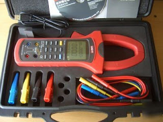 |
| Clamp on Power Factor Meter |
- Since each load has its own
power factor, the measurements should start with each individual machine and
move upward to each distribution panel and finish at the feeder and then to
transformer as shown in the Fig.3 below.
Fig.3
- Measuring power factor is a
costly procedure when it is required to shut the load down and connect in a
metering system to measure the current, voltage and power. So as to avoid the
costly shutdown and time consuming measurement, it is preferable to use a
clamp on power factor meter.
- To connect the meter, the
voltage leads are first connected to the meter and then clipped to the phases
supplying the load. The clamp-on current transformer is then clamped on to
the phase supplying the load. To select the appropriate clamp on CT, a
conventional clamp tester is used to measure the load current. The voltage is
also measured. Now using the clamp-on, power factor meter with appropriate
CT, the power factor reading is noted.
|
Step#2: Make Some
Preliminary Measurements For Current And Voltage
|
This
step is used to get a rough idea of how heavily loaded the plant cables and
transformers are so that the loss savings can be better estimated. The
measurements are also used to help identify potential harmonic problems.
In this step, we will
learn:
- What
are the Measurements used for Calculation of the cable capacity factor?
- What
are the Measurements used for Calculation Transformer Losses?
- How
to determine of the need for harmonic study?
|
Measurements used
for Calculation of the cable capacity factor
Measure
the currents on several of the more significant feeds within the plant.
Compare the current measurements to the ampacity of the cables and estimate a
typical loading factor for the plant's cables. The ratio of measured current
to ampacity is the cable capacity factor needed for the Loss Savings
Worksheet.
Cable Capacity Factor =
Measured Current / Cable Ampacity
|
Measurements used for
Calculation Transformer Losses
Transformers can account for a large percentage of the losses. If the plant has
step-down transformers on the load side of the utility meter, the average load
kVA flowing through these transformers will be determined from the following
formula:
KVA 3-phase
= Ö3 V line-line
I line
Where
the line-line voltage is given in kV (rms) and the current, I, is the rms
line current reading on the same side of the transformer.
So, we need to measure the rms current flowing
into the transformer from either the primary or secondary side of the
transformer, depending on which is the most convenient.
Notes:
- Remember
to compare your measurement with the rated current on the side you measured.
- Consider
only transformers for which capacitors will be placed on the secondary side. Capacitors
don't help losses unless they are placed on the secondary side to reduce the current.
- Exclude
transformers on the utility side of the meter and transformers that will not have
capacitors installed on their secondary circuits.
|
Determination of the
need for harmonic study
- At
this point in the design process, we are simply interested in determining if there
is sufficient cause to include harmonic studies in the cost justification and
we are looking for effects of harmonic sources in the vicinity of the plant,
either within the plant or in neighboring plants.
- This
can be done by measuring at least the main bus voltage and the total load current
with an instrument capable of measuring both total harmonic distortion (THD) and
true rms values.
- The
measured readings can be an indication for Harmonics possibility as follows:
Measured Bus voltage distortion %
|
Harmonics possibility
|
approximately 1%
|
is not necessarily an indication that there are harmonic sources
to be concerned
|
more than 2%
|
There is a strong possibility that there are significant
harmonic sources in the area that could impact a capacitor installation.
|
Notes:
- This
is not to be confused with the 5% upper limit set by some standards. While it
is often acceptable by standards to have a voltage distortion of as much as 5%,
lower values of distortion can cause problems with capacitors if the conditions
are right.
In
fact, there is a possibility of problems for low values of voltage distortion
less than 2% if the system gets into resonance, particularly, if the predominant
harmonics are higher than the fifth.
Measured current distortion %
|
Harmonics possibility
|
10% or more
|
This reading indicates the presence of harmonic sources that
could conflict with capacitor installation.
|
Also,
if there are any existing capacitors in the installation, a good predictor of
potential harmonic problems is the current in the capacitors.
Capacitor rms current
|
Harmonics possibility
|
exceeds 120- 130% of the rated capacitor current
|
it is likely that there are significant harmonic sources.
|
Again,
in this step, we are not necessarily interested in characterizing the harmonic
sources, but only wanting to know of their existence so that we can take them
into account in the economic screening by assuming extra costs will be
incurred.
|
In the
next article, we will continue explaining other steps
for Power
Factor Correction Capacitors Sizing Calculations for Existing Installations. Please,
keep following.
The
previous and related articles are listed in below table:
Subject Of
Previous Article
|
Article
|
- Glossary of Power Factor Correction Capacitors
|
|
- Types of Loads,
- The Power
Triangle,
- What is a power
factor?
- Types of power
factor
- Why utilities charge
a power factor penalty?
- Billing Structure.
|
|
- What causes
low power factor?
- Bad impacts
of low power factor,
- Benefits of
Power Factor correction.
|
|
- How to make
Power Factor Correction?
- Types of
Power Factor Correction Capacitors
- Individual compensation
|
|
- Group compensation,
- Central compensation,
- Hybrid compensation.
- Summary for Power Factor Correction
Capacitors Sizing Calculations Steps
|
|


No comments:
Post a Comment