
Load Calculations for Feeder and Service Neutral
|
Definitions:
Neutral Conductor: is The conductor connected to the
neutral point of a system that is intended to carry current under normal
conditions.
Neutral Point: is The common point on a
wye-connection in a polyphase system or midpoint on a single-phase, 3-wire
system, or midpoint of a single-phase portion of a 3-phase delta system, or a
midpoint of a 3-wire, direct-current system.
|
|
Important!!!
The neutral conductor is
a current-carrying conductor. Many
believe that, because the
neutral conductor is a grounded
conductor, it is safe to work
on it while it is energized. This is a
very dangerous practice that has led to
many serious electric shocks.
|
|
Four examples of a neutral point in a system (see below image)
An example of the first system is a three-phase, four-wire
wye-connected transformer.
An example of the second system is a
single-phase, three-wire system that supplies power to Most of
one-family dwellings.
An example of the third system is
an ungrounded delta system which is
a type of three-phase
delta system that is sometimes used in
industrial facilities
An example of the fourth system is a direct current system used to supply power derived from batteries, power supplies, generators or other
sources to
the loads.
|

|
Important!!!
At the neutral point of the system, the vectorial
sum of the nominal voltages from all other phases within
the system that utilize the neutral, with respect to the neutral
point, is zero potential.
In some type of delta system, not all phases utilize the
neutral; as in below image where phase (B) does not utilize the neutral.
|

|
Important!!!
The neutral load must be calculated in accordance section
220.61 even if the feeder or service is calculated by the NEC standard method
(Part III) or the NEC optional method (Part IV).
|
|
Rule#1: The feeder or service neutral load Basic Calculation
As per NEC section 220.61(A), The
feeder or service neutral load shall be the maximum unbalance of the load
determined by article 220. The maximum unbalanced load shall be the maximum
net calculated load between the neutral conductor and any one ungrounded
conductor.
|
|
Exception for Rule#1:
For 3-wire, 2-phase or 5-wire,
2-phase systems, the maximum unbalanced load shall be the maximum net calculated
load between the neutral conductor and any one ungrounded conductor
multiplied by 140 percent.
|
|
Important!!!
When calculating the
neutral load, it is not necessary to include loads that do not contribute to
the neutral current.
|
Example#1:
A non-dwelling occupancy has a calculated service load of 92 amperes on one phase and 88 amperes on the other phase. The loads have been balanced as evenly as possible. A water heater has a current draw of 19 amperes at 240 volts. The voltage at this panelboard will be single-phase, 120/240 volts. What is the neutral load?
Solution:
Since the water heater is 240 volts, it will not contribute to the neutral current. Therefore, 19 amperes can be omitted from the neutral load calculation.
The neutral load = highest calculated load – water heater Load = 92 – 19 = 73 amperes
Although the feeder conductors must have an ampere rating of at least 92 amperes, the conductor feeding the neutral must have an ampacity of at least 73 amperes.
|
Rule#2: Permitted Reduction in Neutral Load - 1
As per NEC section 220.61(B)(1), When calculating the feeder or service neutral
load, it is permissible to apply a demand factor of 70 percent to household
electric ranges, wall-mounted ovens, counter-mounted cooking units and
electric dryers, where the maximum unbalanced load has been determined in
accordance with Table 220.55 for ranges and Table 220.54 for dryers.
|
Example#2:
What is the minimum neutral load on the service for 5,500-watt clothes dryer installed in a one-family dwelling?
Solution:
When calculating feeder or service neutral loads for clothes dryers, start by finding the feeder or service load.
As per Table 220.54, because there is only one dryer, the minimum service load (at 100 percent) is 5,500 volt-amperes
Apply Rule#2 above; multiply the service load by 70 percent.
So, the minimum neutral load on the service = 5,500 VA × 70% = 3,850 VA
Example#3:
A 10-unit apartment building will have a 12-kW range in each apartment. What load will these ranges add to a service neutral calculation?
Solution:
Start by finding the feeder or service load.
As per column C of Table 220.55 for 10 appliances, the maximum demand for 10 nos. 12-kW ranges is 25 kW.
Apply Rule#2 above; multiply the service load by 70 percent.
The neutral load = 25 KW × 70% = 17.5 kW
|
Rule#3: Permitted Reduction in Neutral Load - 2
As per NEC section 220.61(B)(2), Where the calculated neutral current is more than
200 amperes, another reduction is permitted. Where the feeder or service is supplied
from a three-wire DC or single-phase AC system; a four-wire, three-phase,
three-wire, two-phase system; or a five-wire, two-phase system, it is
permissible to apply a demand factor of 70 percent to that portion of the
unbalanced load in excess of 200 amperes [220.61(B)(2)]. This demand factor
is also in addition to any demand factors that may have already been applied.
|
Example#4:
After calculating the service load for an office building by the NEC Standard calculation, the neutral load is 216,000 volt-amperes. What is the neutral load after applying the demand factor from 220.61(B)(2)? The electrical service will be supplied by a 208Y/120-volt, three-phase, four-wire system.
Solution:
First, convert volt-amperes to amperes. Since this is a 208-volt, three-phase system, the total voltage = 208 V × 1.732 = 360.256 V = 360 V
The neutral Load in Amps = 216,000 VA ÷ 360 V = 600 A
Apply Rule#3 above; multiply the amperes in excess of 200 amperes by 70 %
The amperes in excess of 200 amperes = 600 A – 200 A = 400 A
The demand neutral Load in excess of 200 amperes = 400 A × 70% = 280 A
The total demand neutral load = 280 A + 200 A = 480 A
|
Rule#4: Prohibited Reduction in Neutral Load - 1
As per NEC section 220.61(C)(1), there shall be no reduction of the neutral or
grounded conductor capacity applied to Any portion of a three-wire circuit
consisting of two ungrounded (hot) conductors and the neutral conductor of a
three-phase, four-wire, wye-connected system.
|
|
Important!!!
As per Rule#2 above, it is
permissible to apply an additional demand factor of 70 percent to a feeder or
service neutral supplying household electric ranges. But, As per Rula#4,
applying the 70 percent demand factor is not permissible if the ranges are supplied
by a single-phase panel that is fed from a three-phase, four-wire,
wye-connected system.
|
|
Definition:
Nonlinear Load: A load where the wave shape of the
steady-state current does not follow the wave shape of the applied voltage.
Electronic equipment,
electronic/electric-discharge lighting, adjustable-speed drive systems, and
similar equipment may be nonlinear loads.
|
|
Rule#5: Prohibited Reduction in Neutral Load - 2
As per NEC section 220.61(C)(2), there shall be no reduction of the neutral or
grounded conductor capacity applied to That portion consisting of nonlinear
loads supplied from a 4-wire, wye-connected, 3-phase system.
|
|
Important!!!
As per Rule#3 above, where the
feeder or service-neutral load exceeds 200 amperes, it is permissible to
apply an additional demand factor of 70 percent to that portion of the
unbalanced load in excess of 200 amperes. But, As per Rula#5, applying the 70
percent demand factor to reduce the neutral or grounded conductor’s capacity
is not permissible for that portion consisting of nonlinear loads supplied
from three-phase, 4-wire, wye-connected systems .
|
Example#5:
After calculating the service load for an office building by the basic calculation, the neutral load is 216,000 volt-amperes. The major portion of the neutral load is fluorescent luminaires and information technology equipment. The electrical service will be supplied by a 208Y/120 volt, three-phase, 4-wire system. After demand factors, what is the neutral load in amperes?
Solution:
First, convert volt-amperes to amperes. Since this is a 208-volt, three-phase system, the total voltage = 208 V × 1.732 = 360.256 V = 360 V
The neutral Load in Amps = 216,000 VA ÷ 360 V = 600 A
Apply Rule#5 above; since the major portion of the neutral load consists of nonlinear loads, applying the additional demand factor of 70 percent is not permissible.
This office building has a neutral demand load of 600 amperes
|
Important!!!
If the neutral load calculated as
per 220.61 is less than the calculated load of the ungrounded (hot)
conductors, it might be possible to reduce the size of the feeder or
service-neutral conductor to be smaller than the ungrounded conductors size,
but this is not a must, The installed neutral conductor can be the same size
as the ungrounded conductors.
|
|
Rule#6: Relation between Sizes of Neutral Conductor and Equipment-Grounding
Conductor
Compare the minimum size required
for the neutral calculated load with the minimum size equipment-grounding
conductor from table 250.122 (in below image); then, select the larger of the
two to be the size of the neutral conductor.
|

Example#6:
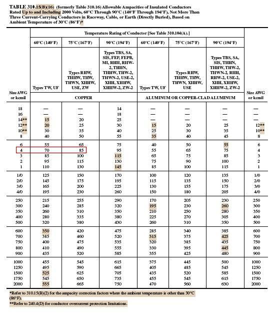
a 400-ampere panelboard (protected by a 400-ampere breaker) will be installed in an area within an industrial plant. The panelboard will be supplied by a 208Y/120 volt, three-phase, 4-wire system. The size of the ungrounded feeder conductors will be 500 kcmil copper. The calculated neutral load is 67 amperes. What is the minimum size conductor required for the neutral?
Solution:
Based on the calculated neutral load only, the minimum size conductor from Table 310.16 is 4 AWG. (See image for table 310.16)
The size equipment-grounding conductor specified in Table 250.122 for a 400-ampere overcurrent device is 3 AWG copper.
Therefore, the minimum size neutral conductor is 3 AWG copper.
|
Rule#6: Relation between Sizes of Neutral Conductor and Grounded
Electrode Conductor
The neutral conductor must not be
smaller than the required grounded electrode specified in table 250.66 (in
below image).
|

In the next article, I will explain the Overcurrent Protection Calculations. Please, keep following.

No comments:
Post a Comment