
In the previous article “ Calculux Software for Lighting Design – Part One “, I explained the main window of Calculux Indoor Software and the dropdown menus in the menu bar.
And in the In the previous article “Calculux Software for Lighting Design – Part Two “. I explained how to check and adjust the default settings of Calculux.
And in the In the previous article “Calculux Software for Lighting Design – Part Three “. I explained Example for lighting design calculations by using Calculux Indoor Software.
Today I will explain the same office but with adding furniture and additional lighting, such as task lighting and accent lighting to the office as follows.
Example #2:
For the same office discussed before in example#1 in our previous article, add the following items:
- Desk consists of (3) elements with dimensions as follows:
- Element#1: 1.6 m x 0.8 m
- Element#2: 0.8 m x 0.8 m
- Element#3: 1.2 m x 0.8 m
- Conference table with dimension = 1.6 m x 0.8 m
- A task lighting for the desk and conference table
- Accent lighting for a painting.
Design a general lighting scheme of this office after adding the above items.
Answer:
Step#1: Open the saved file from example#1 and save it with another name.

- Select Open Project from the File menu.
- Select OFFICE 1.CIN and click OK.

- In the File menu, select Save As.
- In the File Name box, enter OFFICE 2.CIN and click OK.
- You are now working in OFFICE 2.CIN.
Step#2: Adding furniture
By means of the Drawing function a bureau (desk), consisting of three elements, and a conference table will be placed in the room.
- Select Drawings from the Data menu.
1- Placing the first bureau element (dimensions: 1.60m x 0.80m):

- Select Add Rectangle.
- In the Add Rectangle dialogue box, set the following parameters: Name Bureau
- Position of the bottom left corner of the bureau element:
- Dimensions and orientation of the bureau:
- Click OK.
2- Placing the second bureau element (dimensions: 0.80m x 0.80m)

- Select Add Rectangle.
- In the Add Rectangle dialogue box, set the following parameters: Name Bureau corner
- Position of the bottom left corner of the bureau element:
- Dimensions and orientation of the bureau:
- Click OK.
3- Placing the third bureau element (dimensions: 1.20m x 0.80m)

- Select Add Rectangle.
- In the Add Rectangle dialogue box, set the following parameters: Name Bureau left
- Position of the bottom left corner of the bureau element:
- Dimensions and orientation of the bureau:
- Click OK.
4- Placing the conference table (dimensions: 0.80m x 1.60m)

- Select Add Rectangle.
- In the Add Rectangle dialogue box, set the following parameters: Name Conference table
- Position of the bottom left corner of the conference table:
- Dimensions and orientation of the conference table:
- Click OK, then Close.
Note:
The position of the bottom left corner for any furniture is given by the architect.
After adding the furniture the layout will be as follows:

Step#3: Selecting a Project Luminaire for task-and accent lighting
Now task lighting for the desk and conference table and accent lighting for a painting will be added. For this project the MASTERLINE PLUS 20W 24D will be used.
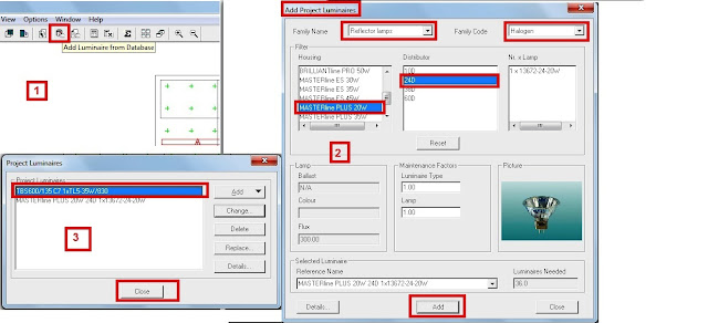
- Click on Toolbar shortcut button.
- Family Name REFLECTOR LAMPS
- Family Code HALOGEN
- Housing MASTERLINE PLUS 20W
- Light distributor 24D
- Click Add, then OK.
Step#4: Repositioning of luminaires for general lighting
Due to windows in the back wall of the room (wall at position Y = 5.6) the luminaires at the window side have to be moved closer towards the window side. There are two possibilities:
A- Change the Y-spacing of the luminaires in the arrangement

- Select Arranged Luminaires from Data menu.
- In the Arrangements dialogue box, click Change.
- Select the Arrangement tab.
- In the Definition box, enter the Y-spacing of the luminaires:
- Change the Y-spacing from 2.80 to 3.40.
- Click OK, then Close.
B- Change the position of the luminaires
According to the arrangement rule, the luminaires in the Room Block arrangement cannot be moved individually. In order to move individual luminaires, the Room Block arrangement has to be changed into a Free arrangement first.

- Select Arranged Luminaires from Data menu. (as in step#4-A)
- In the Arrangements dialogue box, click Free, then click Yes.
- Now the Room Block arrangement is made into a Free arrangement.
- Click Change and select the Luminaire List tab.
- In the Luminaire List tab, enter the new positions of the luminaires:
- Change the Y-position of the luminaires in row 3 and 4 from 4.20 to 4.80.
- Click OK, then Close.
Step#5: Positioning luminaires for the task- and accent lighting
1- Task lighting for the bureau

- In the Arrangements dialogue box, click Add and select Block.
- In the Arrangement tab, enter the name of the arrangement, Name: Bureau
- In the Position A box, enter the position of the bottom left luminaire.
- In the Arrangement box, enter quantity and spacing of the luminaires.
Number in AC: 2 Y-spacing: 0.80 m
- Select the Luminaire Definition tab.
- In the Project Lumnaire box, select: Type MASTERLINE PLUS 20W 24D
- Click Apply, then OK.
2- Task lighting for the conference table

- In the Arrangements dialogue box, click Add and select Block.
- In the Arrangement tab, enter the name of the arrangement, Name: Conference table
- In the Position A box, enter the position of the bottom left luminaire.
- In the Arrangement box, enter quantity and spacing of the luminaires.
Number in AC: 2 Y-spacing: 0.40 m
- Select the Luminaire Definition tab.
- In the Project Luminaire box, select: Type MASTERLINE PLUS 20W 24D
- Click Apply, then OK.
3- Accent lighting for the painting on the right wall

- In the Arrangements dialogue box, click Add and select Line.
- Select the Luminaire Definition tab.
- In the Project Luminaire box, enter: Type MASTERLINE PLUS 20W 24D
- Click Apply.
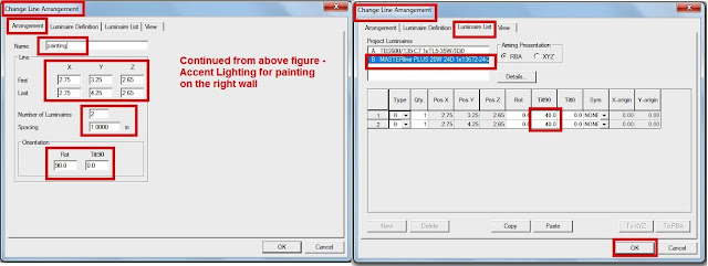
- Select the Arrangement tab and enter: Name Painting
- In the Line box, enter the position, quantity and spacing of the luminaires:
- First X = 2.75, Y = 3.25, Z = 2.65
- Last X = 2.75, Y = 4.25, Z = 2.65
- Number of Luminaires : 2
- Spacing: 1.00 m
- The rotation of the Line arrangement will be 90°.
To ensure that the luminaires fit into the room when they are tilted a luminaire height of 2.65 m is chosen (room height is 2.70 m).
Now the luminaires have to be tilted to the wall:
- In the Luminaire List tab, enter the values for the tilt of both luminaires: Tilt90 = 40°
- Click OK, then Close.
the layout after Luiminaire Positioning will be as follows:

To show that the accent lighting is aimed to the wall, the 'aiming arrows' can be displayed in the project overview.

- Select Project Options from the Data menu.
- In the 2D View tab, check the Aiming Arrows box.
- Click OK.
the layout after showing aiming arrows will be as follows:

Step#6: Define Calculation grids for the bureau, conference table and the right wall
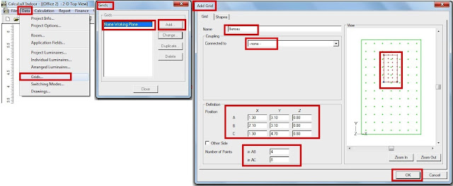
- Select Grids from the Data menu.
1- Grid on Bureau
- In the Grids dialogue box, click Add.
- In the Add Grid dialogue box, enter: Name Bureau
- In the Coupling box, select: Connected to None
- In the Definition box, enter the position of the grid points: Position be as follows:
B X = 2.1, Y = 3.1, Z = 0.8
C X = 1.3, Y = 4.7, Z = 0.8
Note:
- (3) Point positions (A,B &C) must be given for every furniture grid.
- These positions are derived from the position of bottom left corner of the furniture given by architect in step#2.
so, we have two axis AB (X-axis) and AC (Y-axis) as shown in following figure:

- Number of Points in AB = 4 , in AC = 8
The element#1 in bureau has dimension LxW = 1.6 x 0.8, choose the Min. of length and width and perform the following calculation for it:
No. of grid points in X direction = Integral (2W+1) = Integral (2X0.8+1) =3
If you divide width by no. of grid points in X direction, then space between grid points in AB direction = 0.8/3 will not result in a complete number, so let no. of grid points in X direction = 4, then space between grid points in AB direction = 0.8/4 = 0.2
Then, no. of grid points in Y direction = 1.6/0.2= 8
- Do not check 'Other Side'.
- Click OK.
2- Grid on Conference table

- In the Grids dialogue box, click Add.
- In the Add Grid dialogue box, enter: Name Conference table
- In the Coupling box, select: Connected to None
- In the Definition box, enter the position of the grid points: Position will be as follows:
A X = 1.7, Y = 1.0, Z = 0.8
B X = 3.3, Y = 1.0, Z = 0.8
C X = 1.7, Y = 1.8, Z = 0.8
- Number of Points : in AB = 8 , in AC = 4
- Do not check 'Other Side'.
- Click OK.
3- Grid on right wall

- In the Grids dialogue box, click Add.
- In the Add Grid dialogue box, enter: Name Right Wall
- In the Coupling box, select: Connected to Right wall
- Click OK, then Close.
In the next article, I will continue solving this example by using CalcuLux Indoor Software. Please, keep following.

No comments:
Post a Comment