
- Assigning of electrical installation characteristics,
- Assigning of Technological characteristics,
- Using Architecture assessment criteria,
- Step (1): Choice of distribution architecture fundamentals,
- Step (2): choice of architecture details,
- Step (3): choice of equipment,
- Recommendations for architecture optimization.
And I began explaining the second task: Assigning of Technological characteristics which include the following categories or possible values:
- Environment and atmosphere,
- Service Index,
- Other considerations.
Today, I will continue explaining other categories of Technological characteristics.
You can review the following previous topics for more information and good following:
2- Service Index
|
#
|
characteristic
|
Definition
|
choice
|
|
|
2
|
Service Index
|
The service index (IS) is
a value that allows us to characterize an LV switchboard according to user
requirements in terms of operation, maintenance, and scalability.
|
|
111
|
|
|
211
|
|||
|
|
223
|
|||
|
|
232
|
|||
|
|
233
|
|||
|
|
332
|
|||
|
|
333
|
|||
Service Index Code Arrangement:
SI code comprising a group of three numbers as follows:
- First Number: it relates to Operation (setting, measurement, locking, padlocking).
- Second Number: it relates to Maintenance (cleaning, checking, testing, re-paining).
- Third Number: it relates to upgrade (addition, modification, site expansion).
The following table summarizes the values of these numbers:
|
First Number
Operation
(setting, measurement, locking, padlocking)
|
Second Number
Maintenance
(cleaning, checking, testing, re-paining)
|
Third Number
Upgrade
(addition, modification, site expansion)
|
|
|
Level 1
|
IS = 1 • •
|
IS = • 1 •
|
IS = • • 1
|
|
Operation may lead to
complete stoppage of the switchboard
|
Operation may lead to
complete stoppage of the switchboard
|
Operation may lead to
complete stoppage of the switchboard
|
|
|
Level 2
|
IS = 2 • •
|
IS = • 2 •
|
IS = • • 2
|
|
Operation may lead to
stoppage of only the functional unit
|
Operation may lead to
stoppage of only the functional unit, with work on connections
|
Operation may lead to
stoppage of only the functional unit, with functional units provided for
back-up
|
|
|
Level 3
|
IS = 3 • •
|
IS = • 3 •
|
IS = • • 3
|
|
Operation may lead to stoppage
of the power of the functional unit only
|
Operation may lead to
stoppage of only the functional unit, without work on connections
|
Operation may lead to
stoppage of only the functional unit, with total freedom in terms of upgrade
|
As shown form the definition of the service index and the above tables, the service index is related to many Mechanical parameters of the used functional units and switchgear. These parameters include:
- The Protection Index (IP),
- Forms of separation,
- Functional Units configuration.
Explained in the previous post “ The Electrical Distribution Architecture – Part Five “.
It is the classification for the internal separation of enclosures/assemblies by barriers or partitions.
There are four basic forms of separation defined in the standard, with sub criteria’s ‘a’ and ‘b’ as follows:
- FORM 1: An enclosed assembly to provide protection against contact with internal parts, where no internal separation is provided,
- FORM 2: As Form 1, but with separation of all functional units from one another,
- FORM 3: As Form 2, but with separation of all functional units from one another,
- FORM 4: As Form 3, but the incoming and outgoing terminals are also required to be separated from the Busbar system, and from one another.
The following figs (1&2) summarize these basic forms and their sub criteria.
 |
| fig (1): Forms of separation |
 |
| fig (2): Forms of separation Layouts |
3- Functional Units configuration
Any Switchgear is divided into a number of functional units like breakers, starters, etc. each comprising all the electrical and mechanical elements that contribute to the fulfillment of a given function.
The switchgear includes an incoming functional unit and one or more functional units for outgoing circuits, depending on the operating requirements of the installation.
Main types of Functional Units
Three basic technologies are used in functional distribution boards.
 |
| fig (3): Main types of functional units |
1- Fixed functional units (see fig.3)
These units cannot be isolated from the supply so that any intervention for maintenance, modifications and so on, requires the shutdown of the entire distribution board. Plug-in or withdrawable devices can however be used to minimize shutdown times and improve the availability of the rest of the installation.
2- Disconnectable functional units (see fig.3)
Each functional unit is mounted on a removable mounting plate and provided with a means of isolation on the upstream side (busbars) and disconnecting facilities on the downstream (outgoing circuit) side. The complete unit can therefore be removed for servicing, without requiring a general shutdown.
3- Drawer-type withdrawable functional units (see fig.3)
The switchgear and associated accessories for a complete function are mounted on a drawer-type horizontally withdrawable chassis. The function is generally complex and often concerns motor control.
Isolation is possible on both the upstream and downstream sides by the complete withdrawal of the drawer, allowing fast replacement of a faulty unit without de-energizing the rest of the distribution board.
Functional Units Connection types
The electrical connections types of functional units can be denoted by a three letter code as follows:
- The first letter denotes the type of electrical connection of the main incoming circuit,
- The second letter denotes the type of electrical connection of the main outgoing circuit,
- The third letter denotes the type of electrical connection of the auxiliary circuits.
Each letter in above can be one of the following:
- F for fixed connection,
- D for disconnectable connections,
- W for withdrawable connections.
Correspondence between service index and other mechanical parameters
Service Index are related to other mechanical parameters as shown in fig (4)
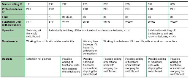 |
| fig (4) |
3- Other considerations
Other considerations have an impact on the choice of technological solutions like:
1- designer experience
The designer experience has a great effect on selecting of the Electrical Distribution architecture and it can be differ from one designer to another in the following points:
- Consistency with previous designs or partial usage of previous designs
- Standardization of sub-assemblies.
- Existence of an installed equipment base.
2- Utilities requirements
Examples: Limits of connection power for LV, Access to MV substation,etc.
3- Technical criteria
Examples: Target power factor, backed-up load power, presence of harmonic generators, etc.
These considerations should be taken into account during the detailed electrical definition phase following the draft design stage.
In the next topic, I will explain the Architecture Assessment Criteria. So, please keep following.

This is a helpful guide for engineers working on power systems distribution projects. Thanks for sharing sharing this!
ReplyDelete