
 |
| Fig (1): Types of Lines |
The actual width of each type of line shall be governed by the size and style of the drawing; the relative widths of the lines shall approximate those shown in Fig (1).
Types of Lines
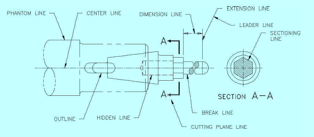 |
| fig (2): All Lines Types |
Center lines shall be composed of long and short dashes, alternately and evenly spaced, with a long dash at each end. Center lines shall cross without voids. (See Fig.1&2)
Very short center lines may be unbroken if there is no confusion with other lines. Center lines shall also be used to indicate the travel of a center. See Fig.2
2- Dimension Lines
Dimension lines shall terminate in arrowheads at each end. They shall be unbroken except where space is required for the dimension (See Fig.1&2).
Another article will be posted giving more information about dimension lines.
3- Leaders Lines
Leaders shall be used to indicate a part or portion to which a number, note, or other reference applies i.e. a connection between the part and the note (See Fig.1&2), and shall be an unbroken line terminating in an arrowhead, dot, or wavy line. Arrowheads should always terminate at a line; dots should be within the outline of an object.
4- Break Lines
Short breaks shall be indicated by solid freehand lines. For long breaks, full ruled lines with freehand zigzags shall be used. Shafts, rods, tubes, etc., which have a portion of their length broken out, shall have the ends of the break drawn as indicated in (Fig.1&2&3).
 |
| Fig (3): Break Lines |
5- Phantom Lines
Phantom lines shall be used to indicate the alternate position of parts of the item delineated, repeated detail, or the relative position of an absent part and shall be composed of alternating one long and two short dashes, evenly spaced, with a long dash at each end. See (Fig.1&2&4).
 |
| Fig (4): Phantom Lines |
6- Sectioning Lines
Sectioning lines shall be used to indicate the exposed surfaces of an object in a sectional view. They are generally thin full lines, but may vary with the kind of material shown in section (see fig 1&2)
7- Extension Lines
Extension lines are used to indicate the extension of a surface or to point to a location outside the part outline. They start with a short, visible gap from the outline of the part and are usually perpendicular to their associated dimension lines (see fig 1&2).
8- Hidden Lines
Hidden lines shall consist of short dashes, evenly spaced. These lines are used to show the hidden features of a part or parts below or behind an object. They shall always begin with a dash in contact with the line from which they begin, except when such a dash would form a continuation of a full line. Dashes shall touch at corners, and arcs shall begin with dashes on the tangent points (see fig 1&2).
9- Stitch Lines
Stitch lines shall be used to indicate the stitching or sewing lines on an article and shall consist of a series of very short dashes, approximately half the length of dash or hidden lines, evenly spaced. Long lines of stitching may be indicated by a series of stitch lines connected by phantom lines (see fig 1).
10- Outlines or Visible Lines
The outline or visible line shall be used for all lines on the drawing representing visible lines on the object (see fig 1&2).
11- Datum Lines
Datum lines shall be used to indicate the position of a datum plane and shall consist of one long dash and two short dashes evenly spaced (see fig 1).
12- Cutting-Plane/Viewing-Plane Lines
The cutting-plane lines shall be used to indicate a plane or planes in which a section is taken. The viewing-plane lines shall be used to indicate the plane or planes from which a surface or surfaces are viewed. On simple views, the cutting planes shall be indicated as shown in Figure 9 on page 31. View shall be shown in back of the cutting plane (3rd angle). (see fig 1&2&5).
 |
| fig (5): Cutting-Plane/Viewing-Plane Lines |
On complex views, or when the cutting planes are bent or offset, the cutting planes shall be indicated as shown in Fig.6
 |
| fig (6) |
In the next Topic, I will explain the line weights and scale. so, please keep following.

No comments:
Post a Comment