in the previous Topic, we talk about five Equipments from Intermediate Stage Equipments and today we will continue with other Intermediate Stage Equipments
10- crossover:
Audio crossovers are a class of electronic filter used in audio applications , Crossovers split the audio signal into separate frequency bands that can be separately routed to loudspeakers optimized for those bands and are used in every speaker system with more than one type of component.
A common speaker system would be the two-way speaker which would include a crossover to divide the sound into low frequencies (bass) for the woofer and high frequencies (treble) for the horn or tweeter. This prevents bass frequencies from getting to the tweeter or horn and damaging it as well as preventing treble frequencies from getting to the woofer and making it sound less pleasing.
A- Classification based on components
Crossovers can be classified based on the design approach; by the type of components used to :
- passive
- Active
fig.1
If the crossover is inside the speaker cabinet it is usually “passive” which means that it only requires that you hook an amplifier up to it and it works as it was designed.
see fig.2 for Passive Crossover schematic.
fig.2
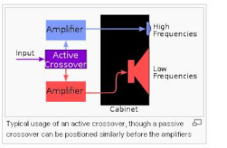
b- active (see fig.3)
is far more complicated and requires that you have a separate amplifier for every component in the system. It splits the sound into two or more parts before it gets to the amplifiers and then each amplifier supplies the correct part of the sound to only one type of component.
fig.3
These crossovers are usually one rack space high and have several controls on them. The controls allow the user to tune in what frequencies those are supposed to go to each component plus set the volume level of each. Although active crossover systems are more complicated and expensive, they are more efficient and sound better. There are a few systems on the market now which have active preset crossovers and amplifiers for each component built into the cabinet. This makes for a remarkable sounding speaker cabinet because the amplifiers, crossovers and speakers are all matched for optimum performance. They do, however, require that they be plugged into the wall and are heavier than regular speaker cabinets.
B- Classification based on circuit topology (see fig.4)
Series and parallel crossover topologies. The HPF and LPF sections for the series crossover are interchanged with respect to the parallel crossover since they appear in shunt with the low & high frequency drivers.
fig.4
Parallel crossovers are by far the most common. Electrically the filters are in parallel and thus the various filter sections do not interact. This makes two-way crossovers easier to design because the sections can be considered separately, and because component tolerance variations will be isolated. In the years before computer modeling, three-way crossovers were designed using the same value, but the advent of iterative design software has taught that this old technique creates excess gain and a 'haystack' response in the midrange output, together with a lower than anticipated input impedance.
b- Series
In this topology, the individual filters are connected in series, and a driver or driver combination is connected in parallel with each filter. To understand the signal path in this type of crossover, refer to the "Series Crossover" figure, and consider a high frequency signal that, during a certain moment, has a positive voltage on the upper Input terminal compared to the lower Input terminal. The low pass filter (LPF) presents a high impedance to the signal, and the tweeter presents a low impedance; so the signal passes through the tweeter. The signal continues to the connection point between the woofer and the high pass filter (HPF). There, the HPF presents a low impedance to the signal, so the signal passes through the HPF, and appears at the lower Input terminal. A low frequency signal with a similar instantaneous voltage characteristic first passes through the LPF, then the woofer, and appears at the lower Input terminal.
c- Derived
Derived crossovers include active crossovers in which one of the crossover responses is derived from the other through the use of a differential amplifier. For example, the difference between the input signal and the output of the high pass section is a low pass response. Thus, when a differential amplifier is used to extract this difference, its output constitutes the low pass filter section. The main advantage of derived filters is that they produce no phase difference between the high pass and low pass sections at any frequency. The disadvantages are either:
(a) that the high pass and low pass sections often have different levels of attenuation in their stop bands, i.e. their slopes are asymmetrical, or
(b) that the response of one or both sections peaks near the crossover frequency, or both.
In case (a), above, the usual situation is that the derived low pass response attenuates at a much slower rate than the fixed response. This requires the speaker to which it is directed to continue to respond to signals deep into the stopband where its physical characteristics may not be ideal.
In the case of (b), above, both speakers are required to operate at higher volume levels as the signal nears the crossover points. This uses more amplifier power and may drive the speaker cones into non-linearity.
In the next Topic, I will explain the Output Stage , please keep following


Why are you absent.
ReplyDeleteIt is good that you started a blog about electrical engineering. The more the merrier.
ReplyDeletethanks
Right. What's a haystack response?
ReplyDelete