

Title Block
The Title block of single-sheet drawings, first sheets of multi-sheet drawings shall appear as shown in either Fig.1 (dimensional system/inches) or Fig.2 (dimensional system/millimeters).
The information required in the Title block shall be as specified or referenced by items 1 through 23 below.
The Title block of continuation sheets for multi-sheet drawings shall contain information listed in items 1, 2, and 4 through 11.
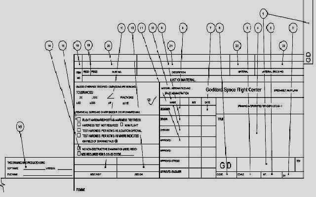

1 DRAWING NO.: we will explain latter how to put a drawing No.
2 “SH OF”: Enter sheet number as applicable. Indicate total sheets only on sheet 1.
3 WT: Enter unit weight calculated at time of design if required.
4 TITLE: drawing title and drawing title size.
5 SCALE: Enter scale. We will explain latter how to select a scale.
6 CODE: indicate code for the drawing preparation party.
7 DATE: Enter date of initials.
8 DESIGNER: Enter designer's printed name and initials.
9 DRAWN: Enter draftsman's printed name or if drawn by the designer, enter
the designer’s printed name
10 CHECKED: Enter design analyst's printed name.
Note: This name shall be an independent name from all other names on the drawing.
11 APPROVED: Enter the printed names of personnel assigned to approve the drawing.
12 USED ON: Enter acronym name of program and subsystem or experiment where applicable.
13 NEXT ASSY: Enter drawing number on which the part is next utilized, modified, or assembled.
14 EXAMINATION: The appropriate “Non-Destructive Examination (NDE)
Required” block shall be checked off, and the addition of the applicable code or “see note XX” shall be added where required.
15 FLIGHT HARDWARE and HARDNESS TESTING: The Flight Hardware block must be checked off when the part is used in actual flight configurations. The appropriate Hardness Testing block shall be checked off regardless of whether the part is flight hardware or not.
16 On CAD-produced drawings, add a 3.5-inch-long by 0.88-inch-high block as follows:
THIS DRAWING WAS PRODUCED USING:
SOFTWARE: (a) VERSION: (b)
FILENAME: (c)
Notes:
(a) Software used (example: “AUTOCAD”)
(b) Version of software (example: “10c7”)
(c) Filename (example: “GSFC1234”)
17 METRIC/HYBRID METRIC-INCH: Add “X” to type of drawing block.AAAA
18 ITEM NO.: Enter item numbers when more than one type of material or part is required.
19 REQD: Enter quantity of parts required only for the parts of an inseparable assembly or assembly drawing.
20 PART NO.: Enter identifying part numbers when required (Government, contractor, vendor, or other). On new drawings, group like items together.
21 DESCRIPTION: Enter material description (plate, etc.) or a part name title if it is another drawing.
22 MATERIAL: Enter the material from which the part is fabricated. Examples: “AL ALY”; “CRES”
23 MATERIAL SPEC.: Enter the applicable material specifications, number, and final condition.
Revision Block
The information required in the revision block fig.3 shall be as specified or referenced by items 24 through 28.

24 REVISIONS - SYM: Enter revision symbol.
25 REVISIONS - ZONE: Enter zone (where used).
26 REVISIONS - DESCRIPTION: Enter description of the revision
27 REVISIONS - DATE: Enter date approved by authorized signer(s) in block.
28 REVISIONS - APPROVAL: Enter signature of person assigned to approve.
in the next Topic, we will continue explaining the Basic Layout components - Legends & Zoning.

No comments:
Post a Comment